Below are instructions for building ICSP programming shield project.
This is one of our easier projects. If you have soldered together any of our earlier projects, this one should be a piece of cake
The order of assembly given below is a suggestion, but there is nothing wrong with soldering the parts in a different order.
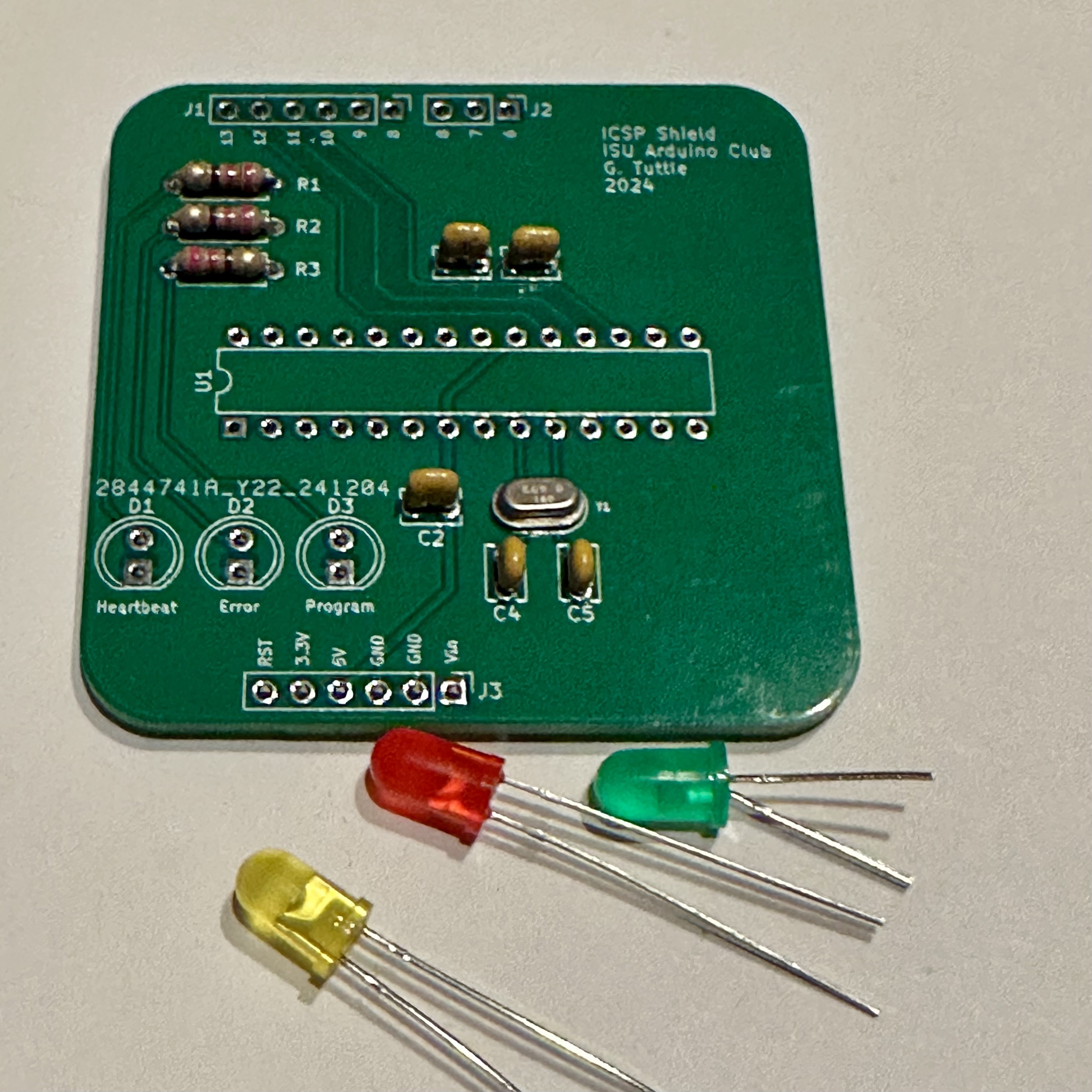
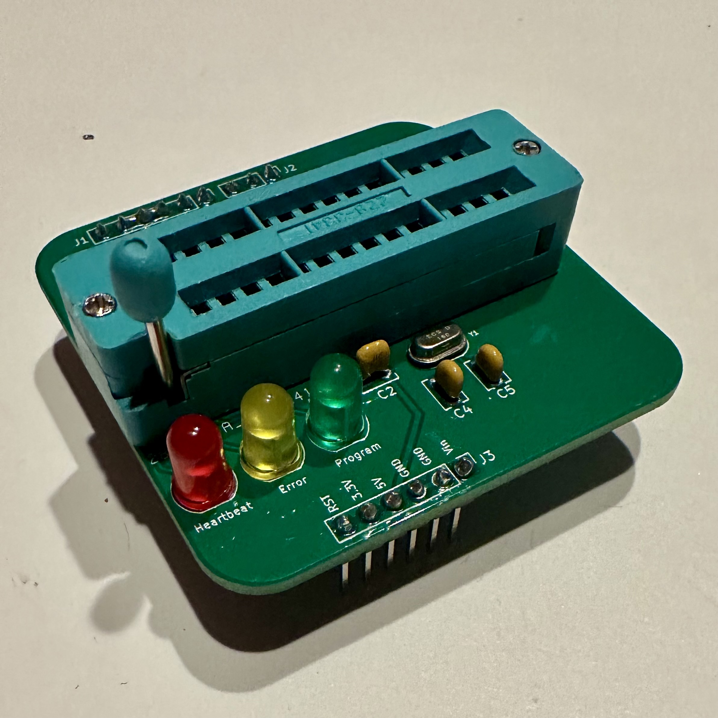
The LEDs that come with the kit are entirely optional. Their only purpose is to give some indiction that the shield is working and that programming is in progress. Note that the "Error" LED always turns on at the end of the programming sequence. As far as I can tell, it serves more as a "programming complete" indicator.
The usual tools are required: solder and soldering iron, needle-nosed pliers for manipulating parts and pulling leads, and wire cutters for trimming leads after soldering.
Of course, as a shield, this is meant to be used with an Arduino R3. Without having that first, this shield is not very useful.
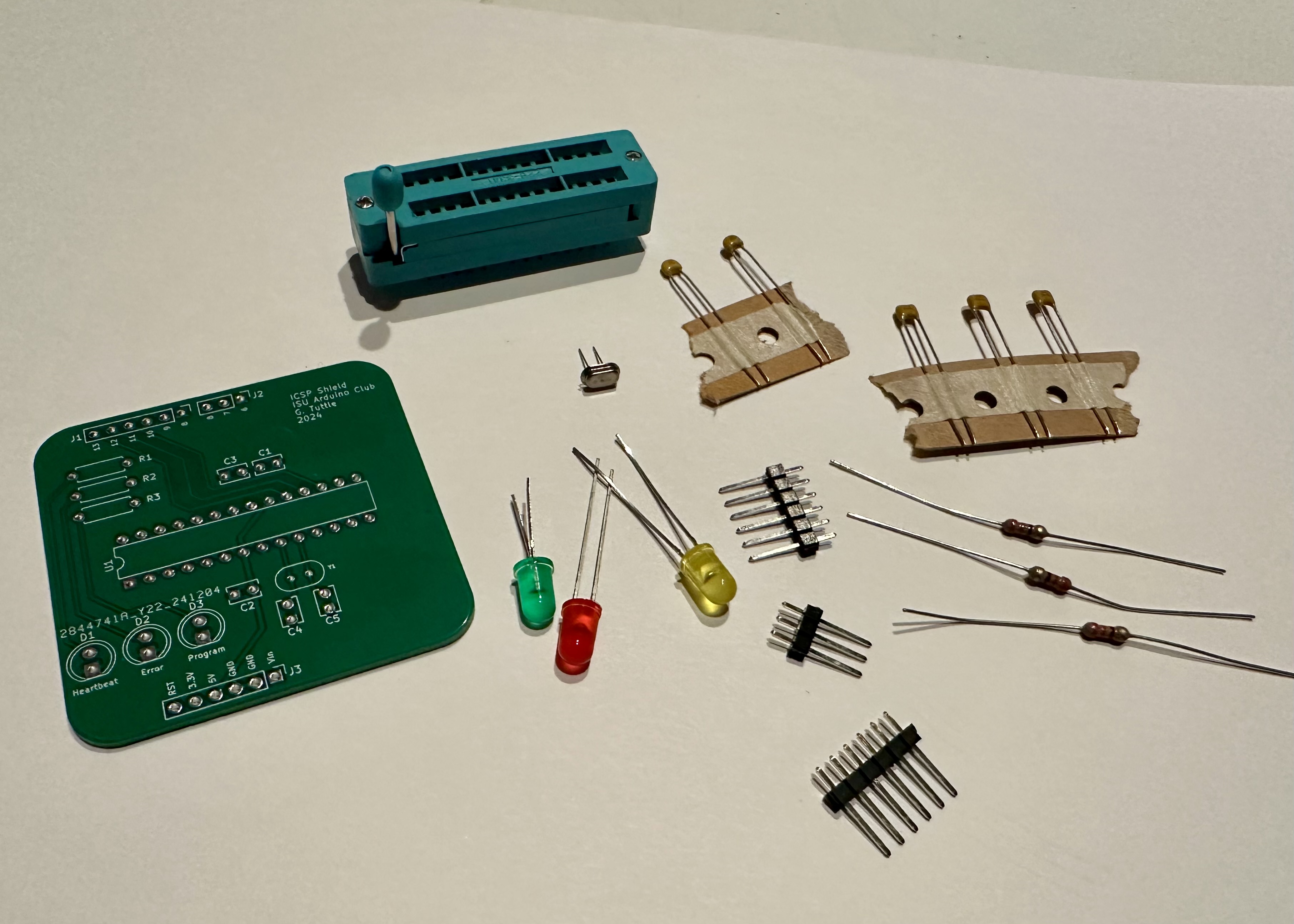
- Assemble the parts. (See the BoM for the complete list.)
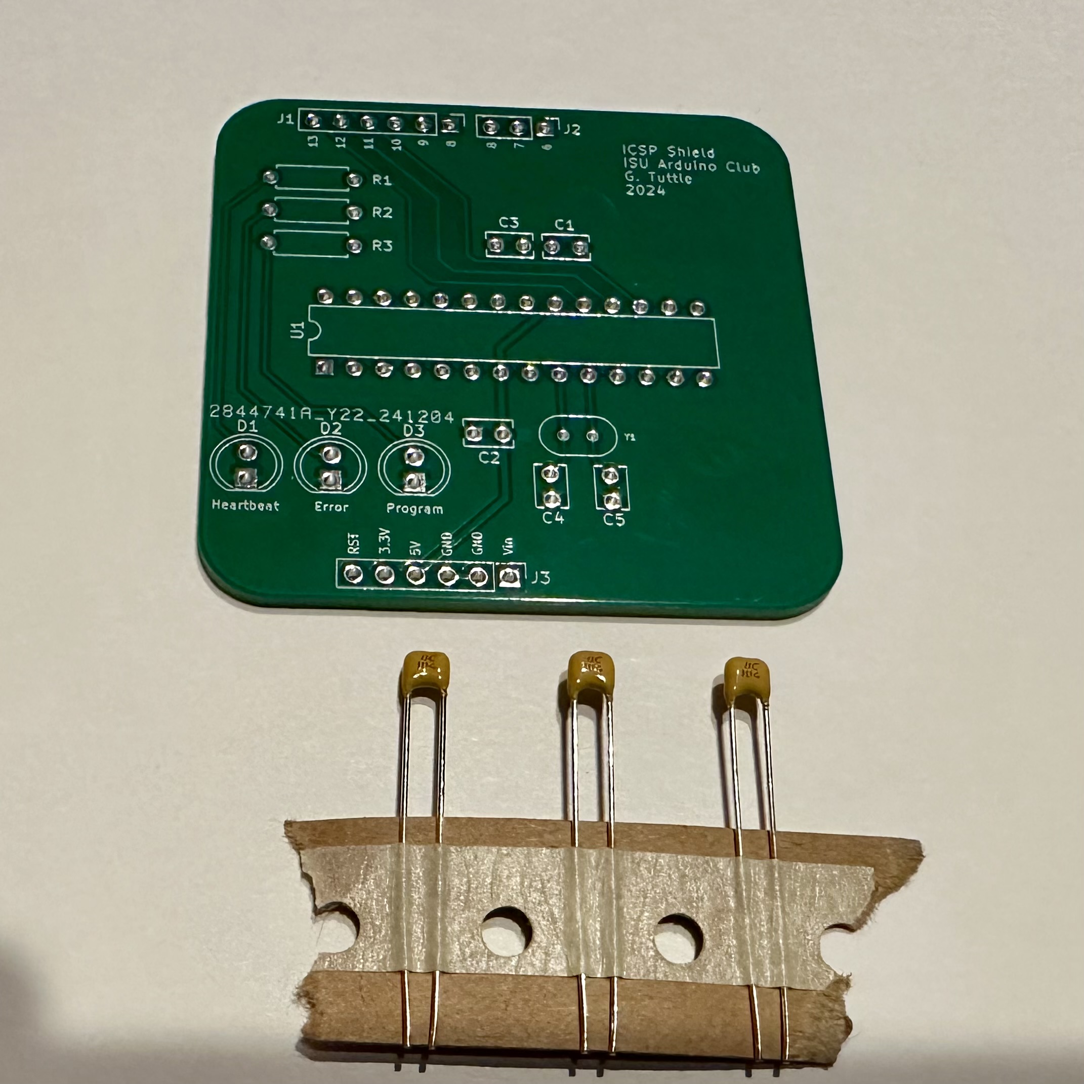
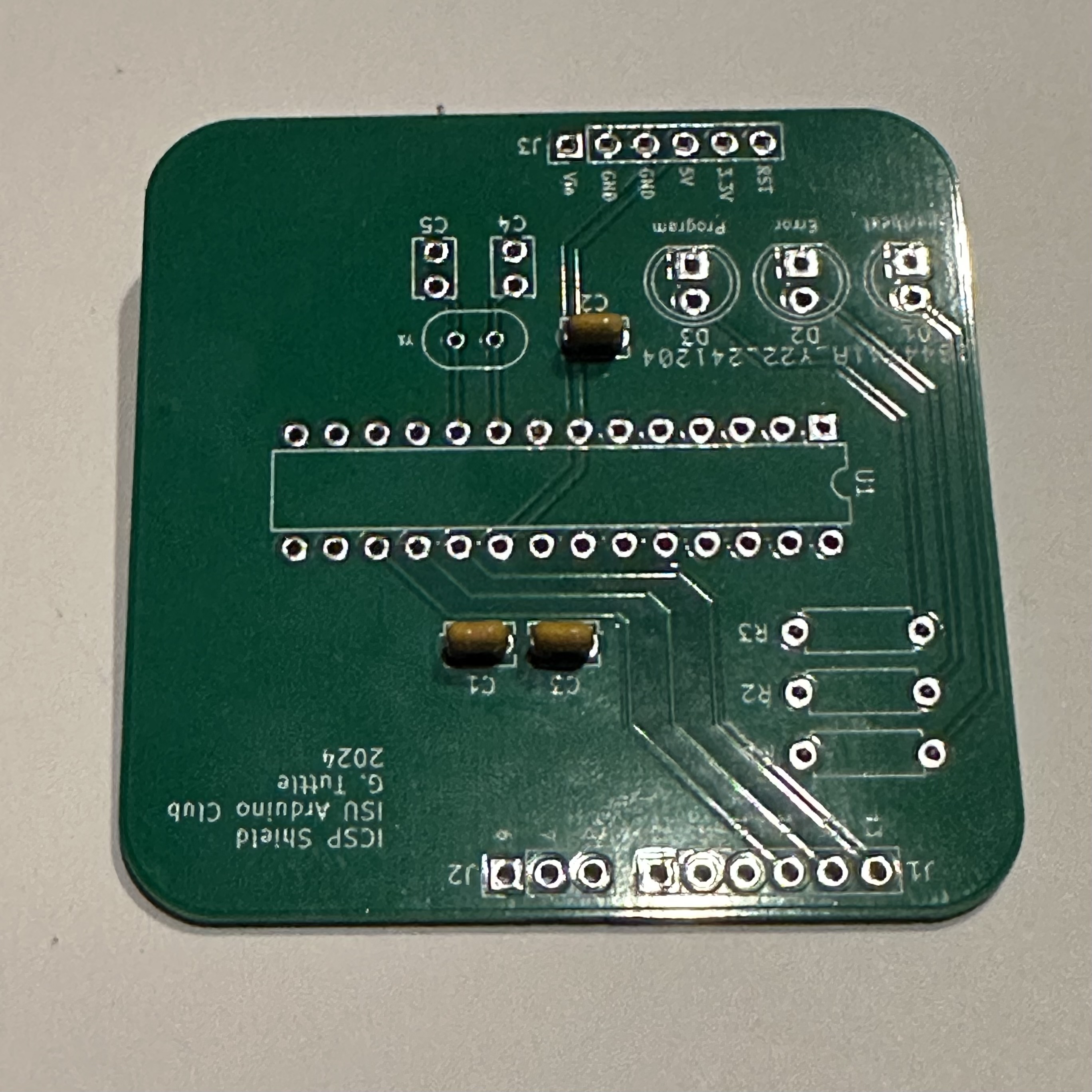
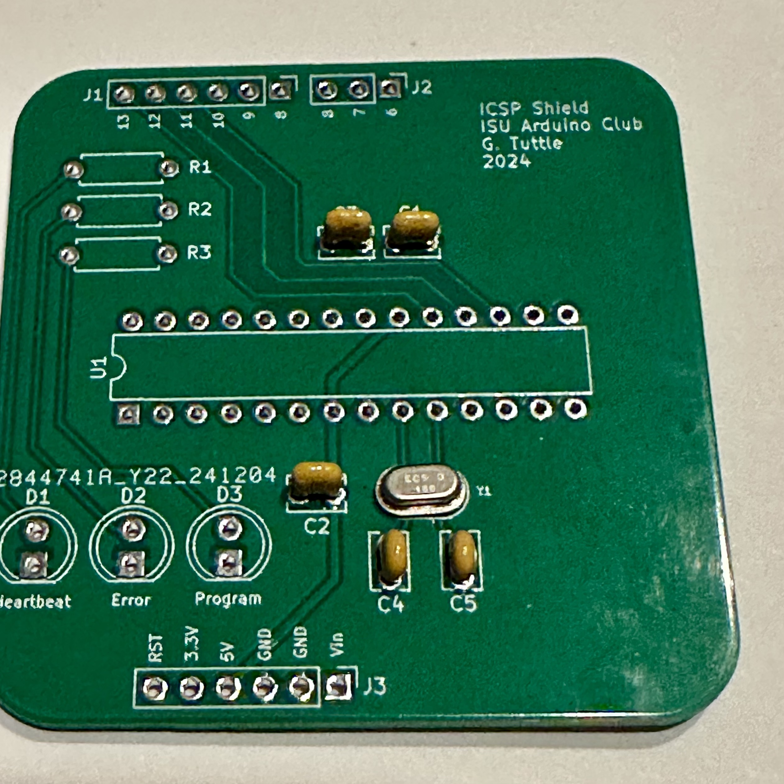
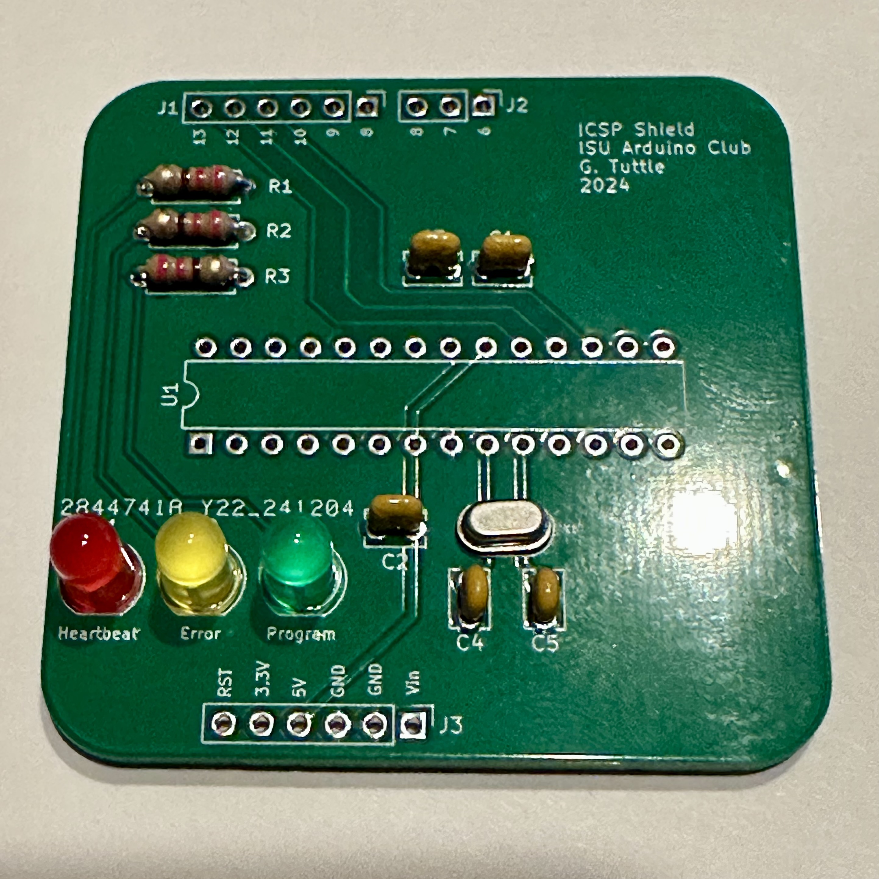
- Solder in the three 100-nF bypass capacitors. The locations are labeled C1, C2, and C3 on the board.
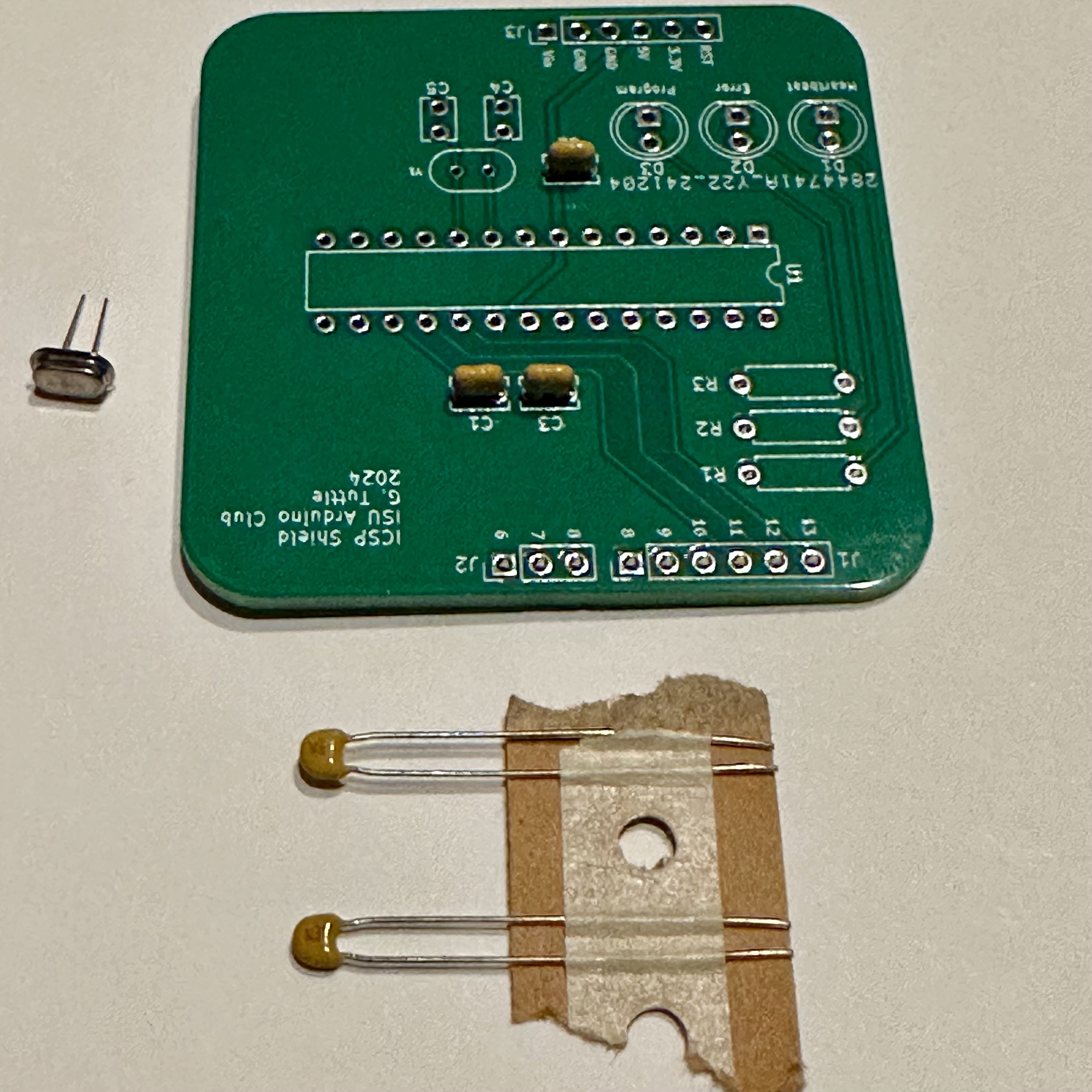
- Next, add the oscillator crystal and its two 22-pF biasing capacitors, labeled C4 and C5.
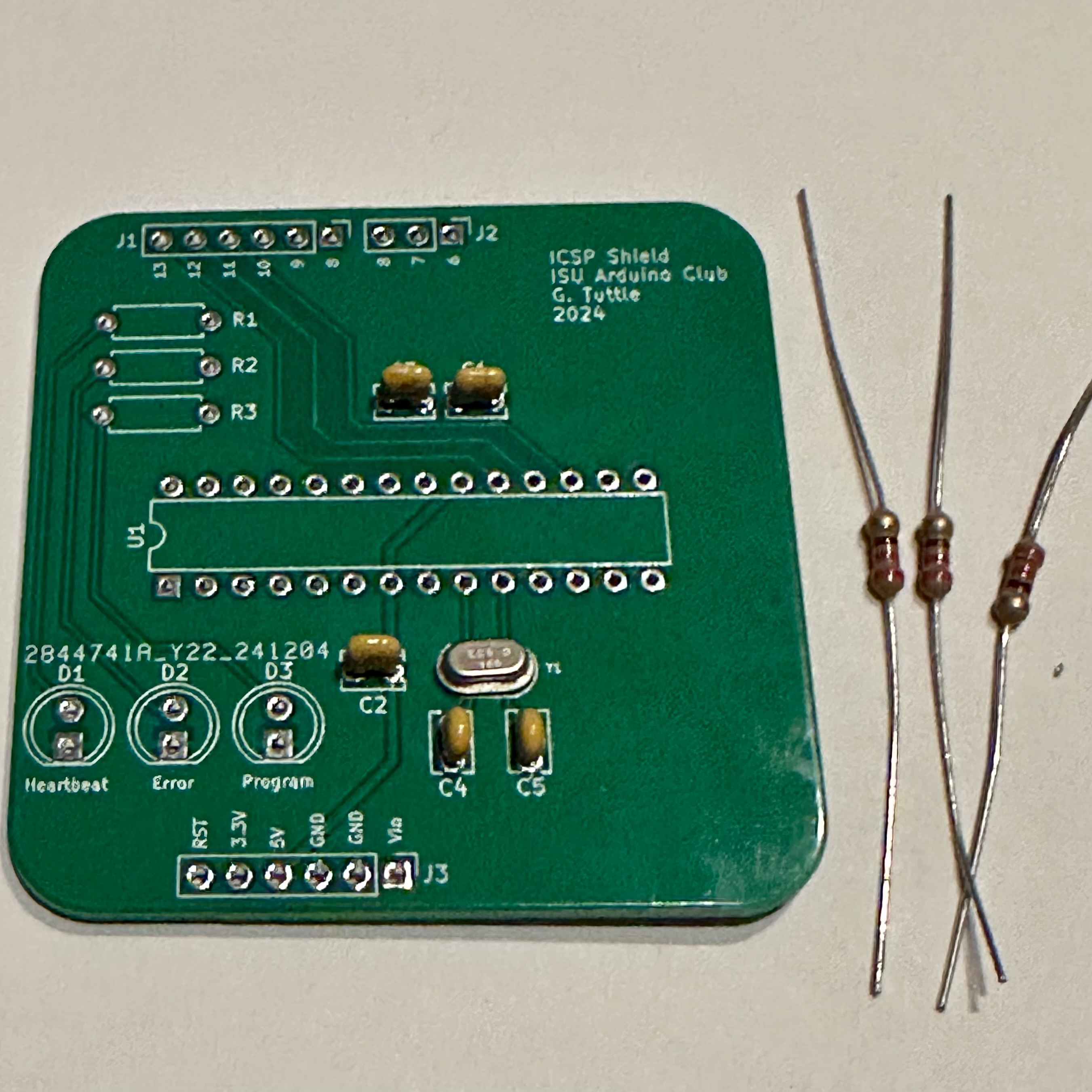
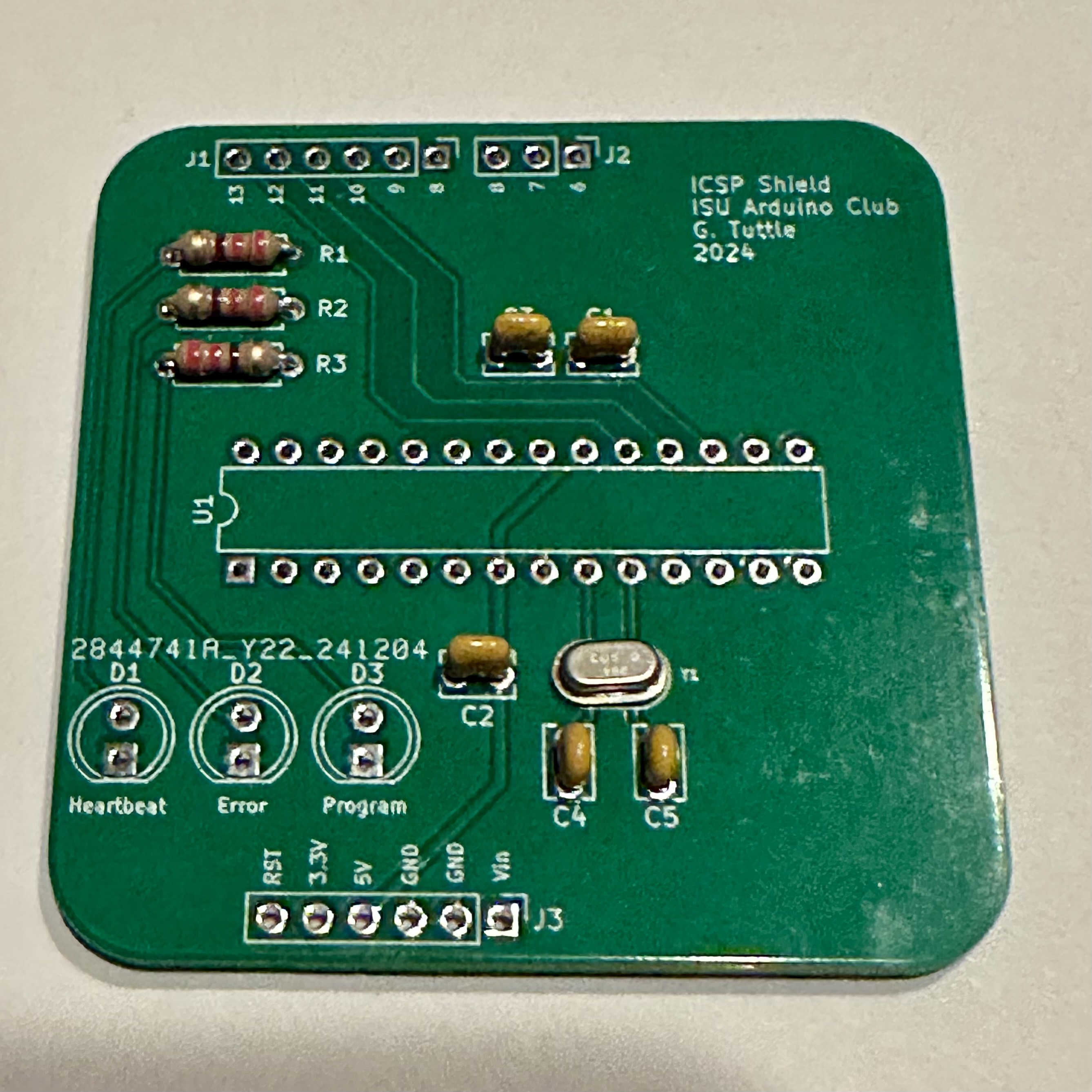
- Now solder in the three 220-Ω LED current-limiting resistors. (Not needed if you choose to leave off the LEDs.)
- Three LEDs. The choices for colors aren't important, but I used red of the "Heartbeat", yellow for "Error", and green for "Program". Remember that LEDs are polarized, so solder them in with the correct orientation.
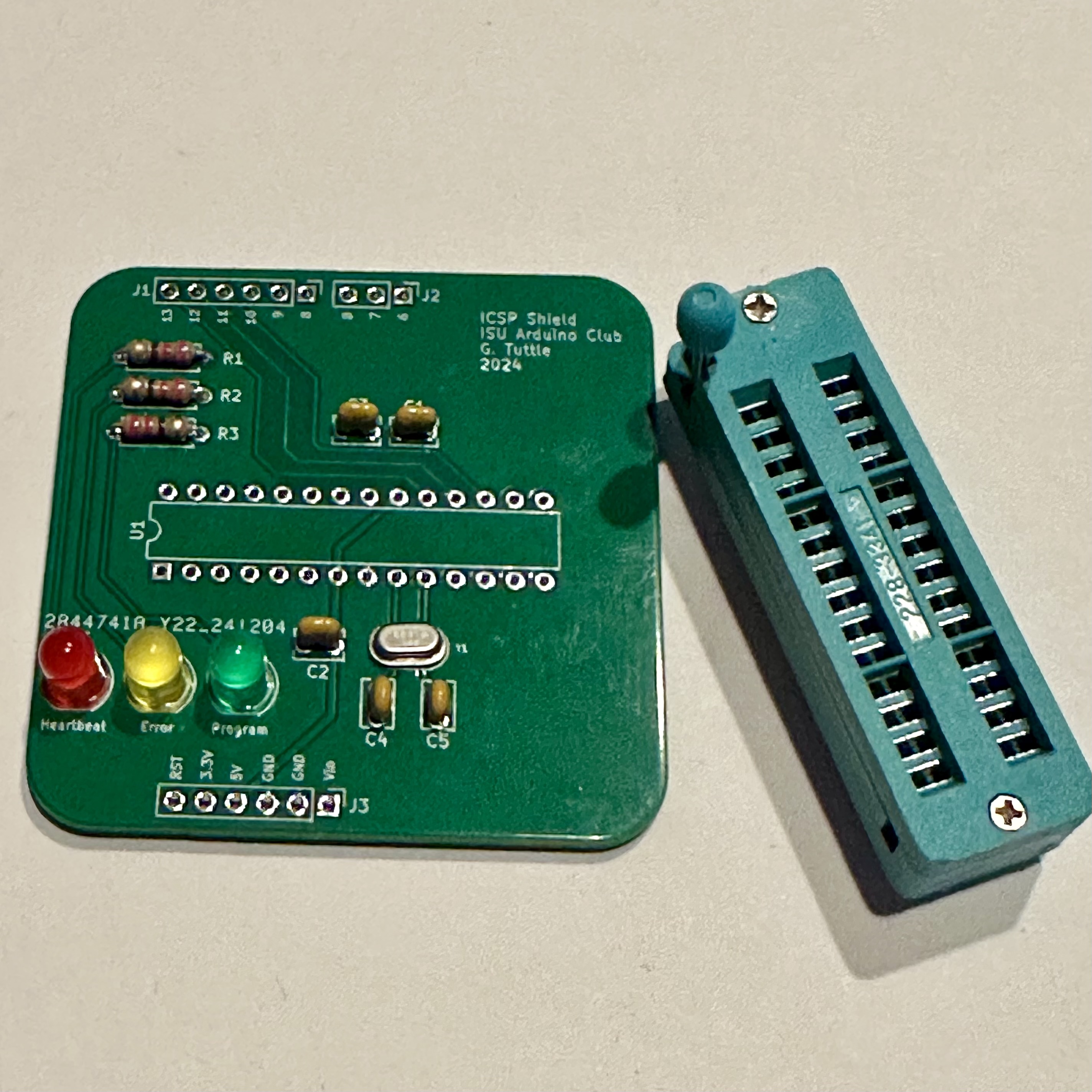
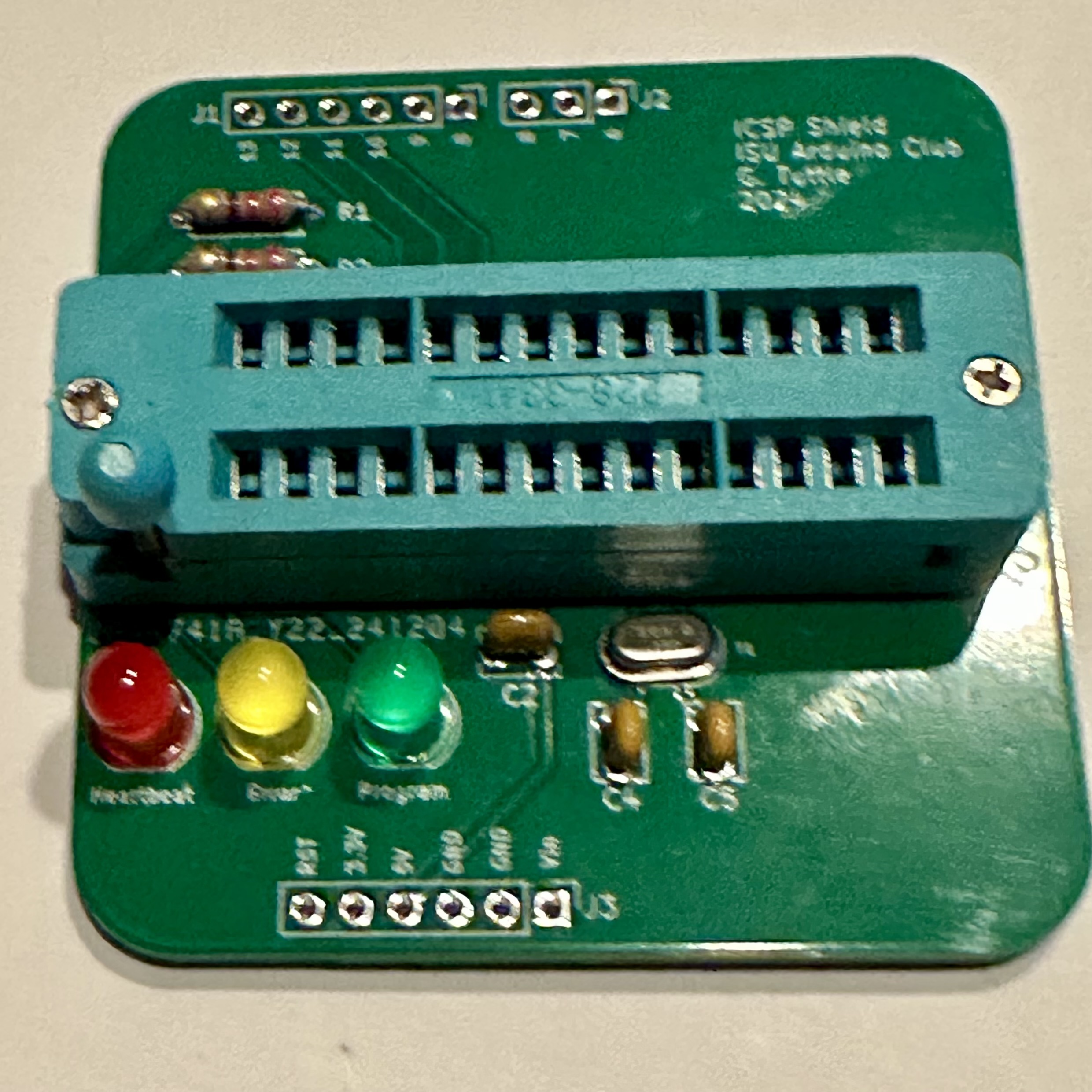
- Now the main thing: the "zero insertion force (ZIF)" socket. This is what makes the programming shield easy to use.
As always when soldering multi-pin parts, start by soldering just one pin. Then check the alignment. If the ZIF is not flush or somehow misaligned, then melt the solder on the one pin and re-postion the part while the solder is melted. Once it looks good, then solder the remaining pins.
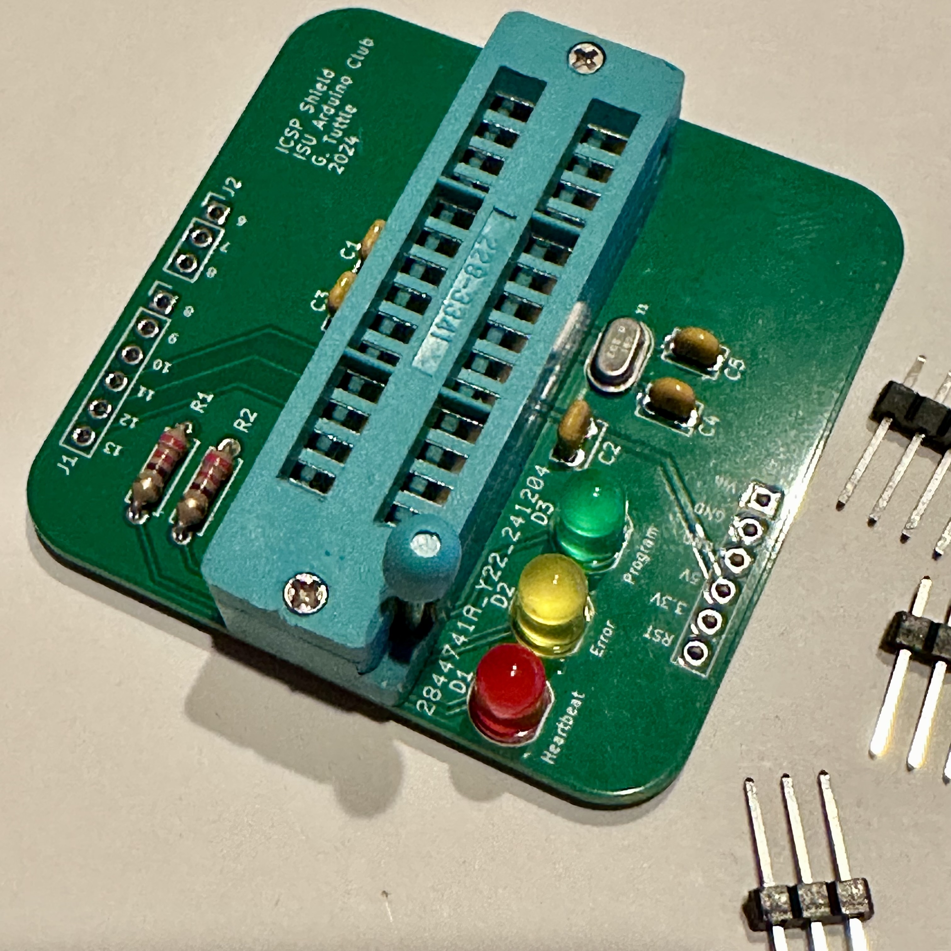
Note that the orientation of the ZIF is not important. You can reverse it if you prefer. However, when an Atmega chip is mounted in in the ZIF, it must match the outline on the board — the chip "notch" must be pointed to the LED side of the board. Otherwise the power, ground, and oscillator pins will be wrong.
- Finally, solder in the header pins. These must line up properly so that the shield can be plugged into an Arduino. Use the soldering advice for multi-pin parts given in Step 6 above.
That's it! The shield is ready to use with an Arduino to program Atmega chips directly. See the notes on chip programming.