ISU Audio and Arduino Club
GTDT amp build instructions
- Below are step-by-step instructions for building the GTDT amplifier project.
- As always, the components shown in the photos may not be identical to those in the kits. In particular, the resistors used here are 1%, whereas the kits come with 5% resistors.
- The order of assembly given below is a suggestion; there is nothing wrong with soldering the parts in a different order.
- The usual tools are required: solder and soldering iron, needle-nosed pliers for manipulating parts and pulling leads through holes, and wire cutters for trimming leads after soldering. Helpful but not essential would be a vise for holding the boards and a magnifying glass and light for viewing small print.
- To view the photos at higher resolution, open the images in a new tab or window.
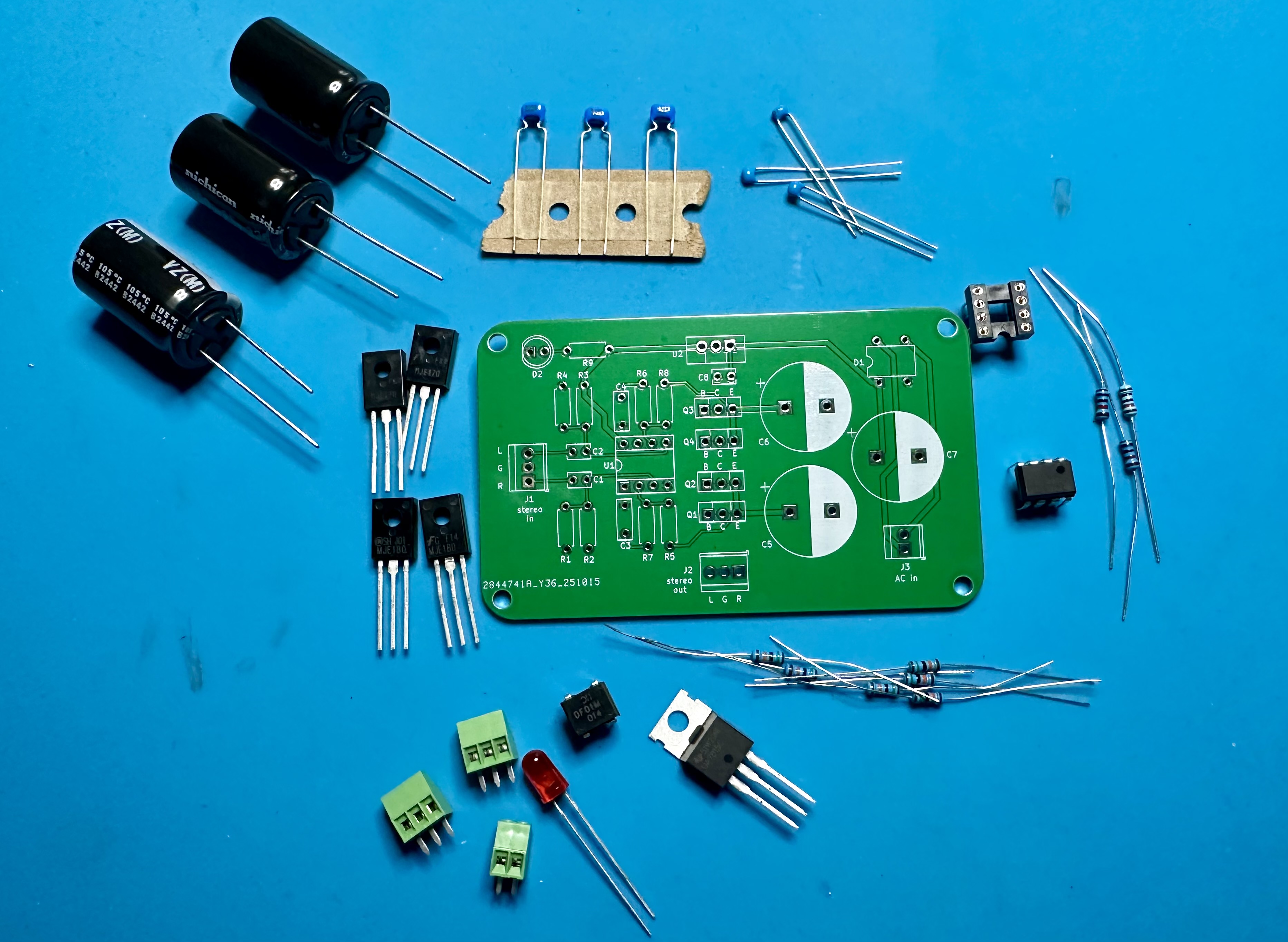
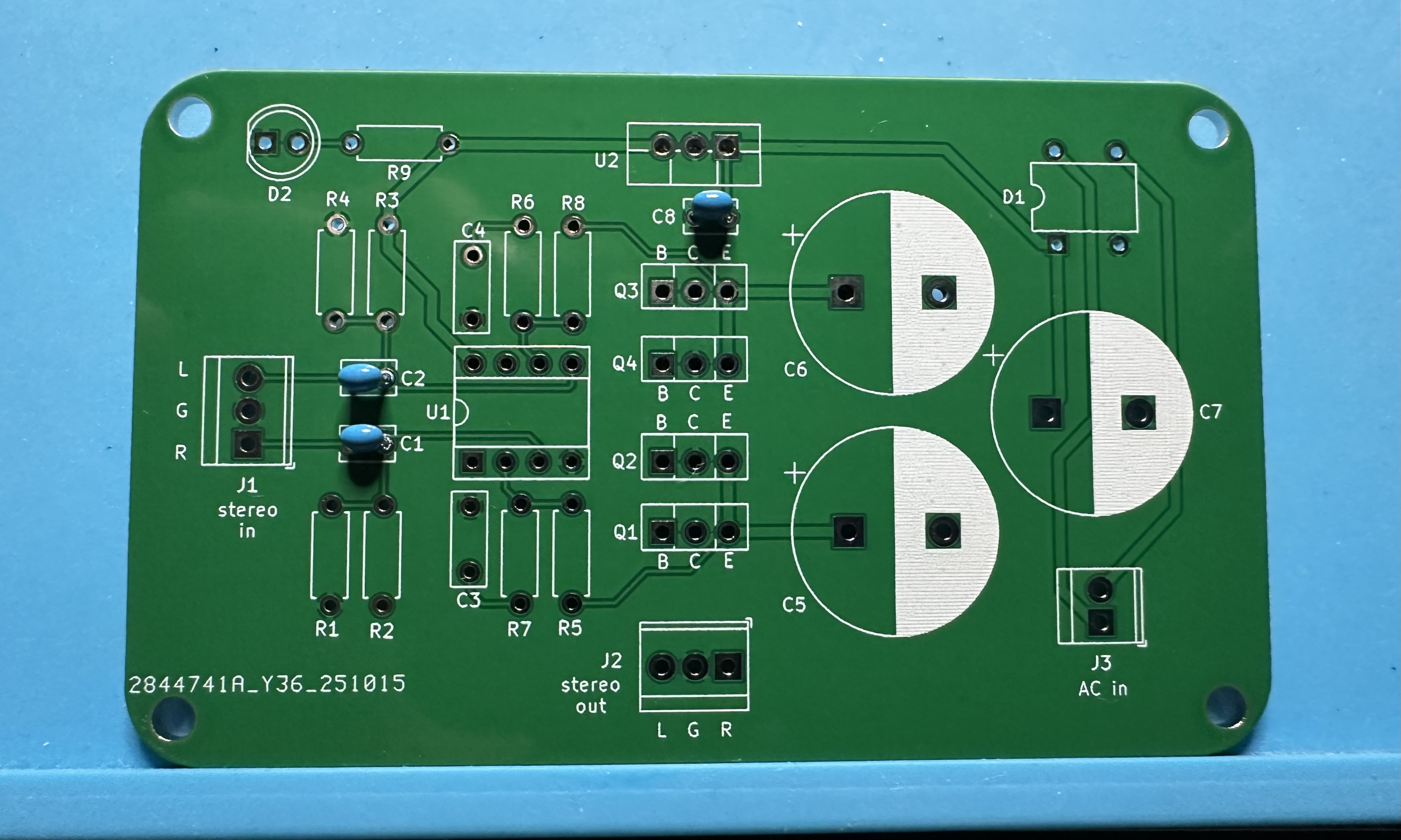
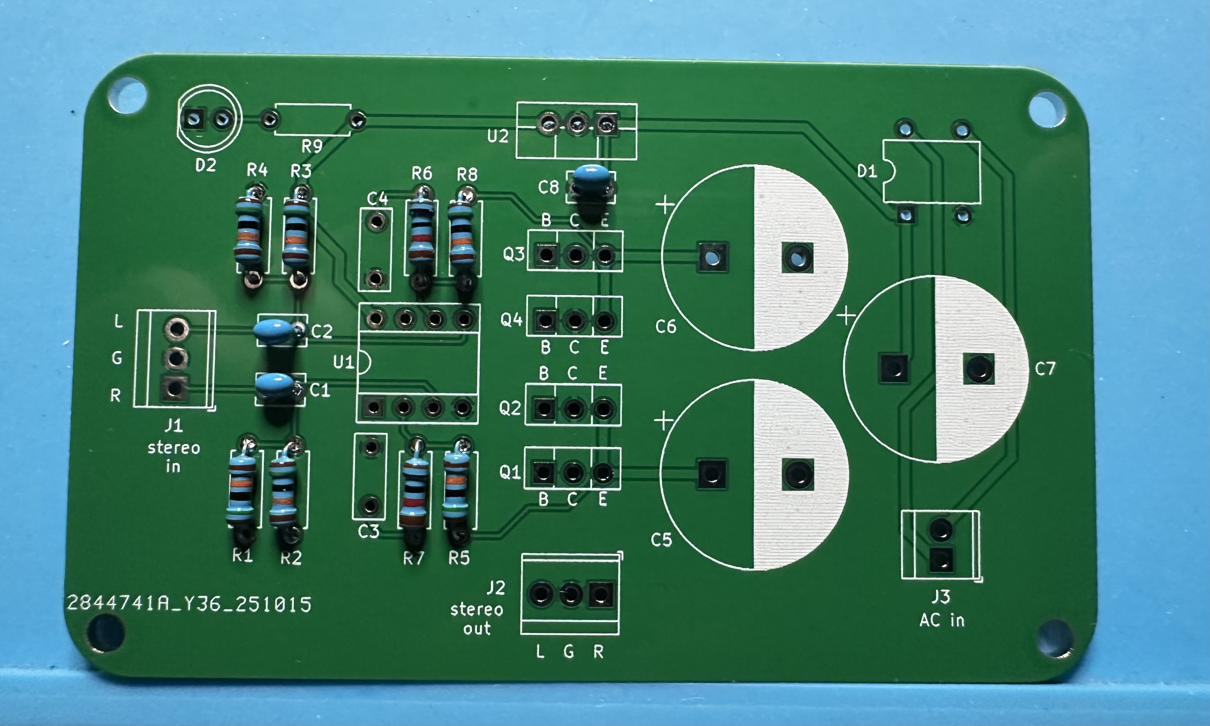
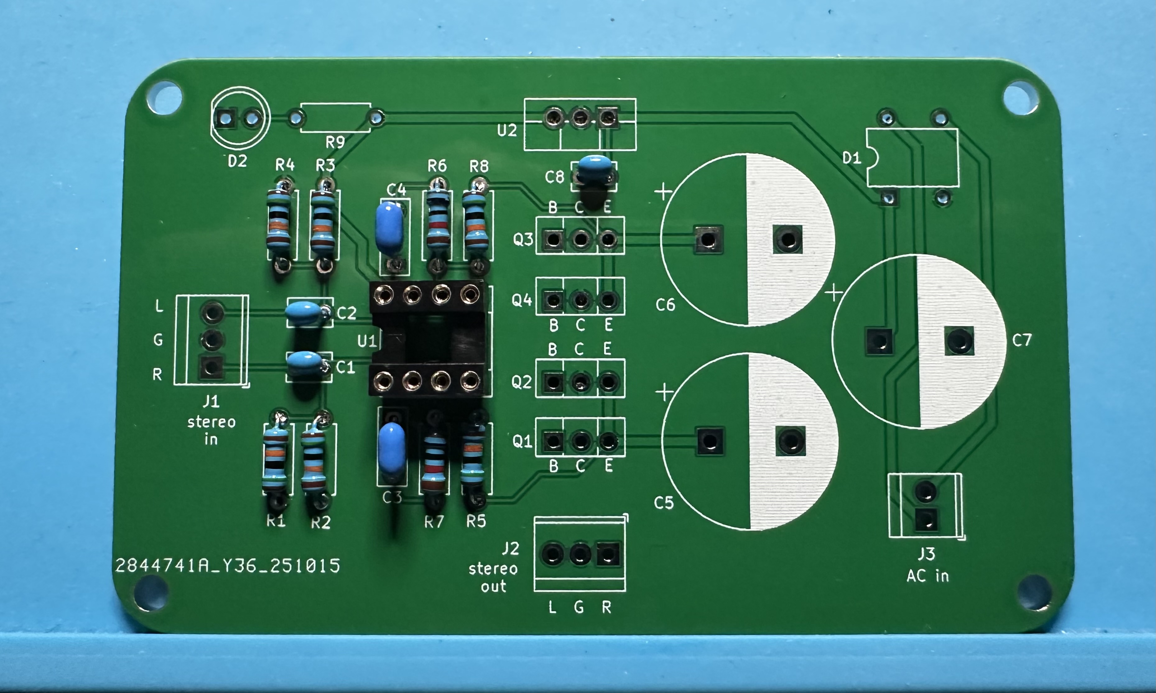
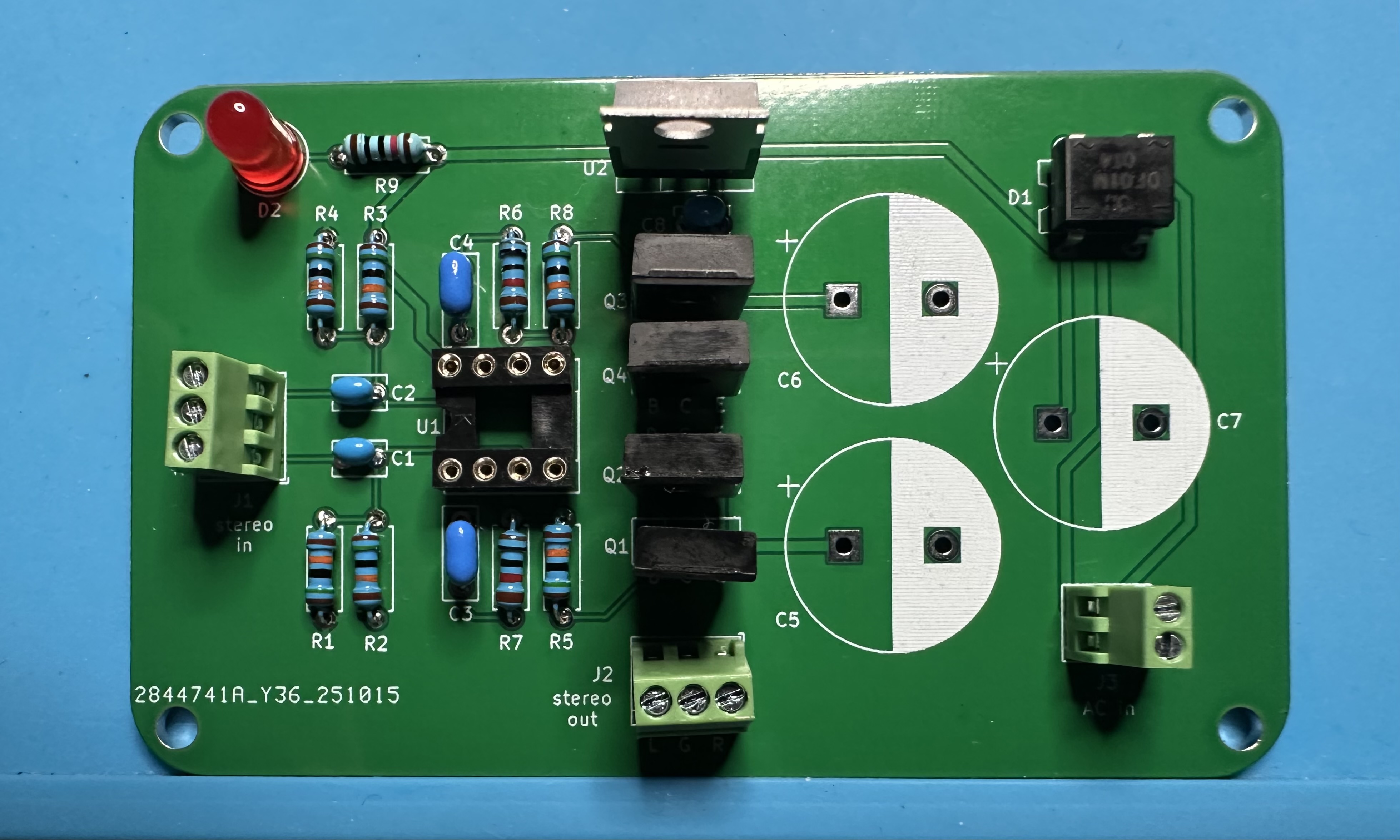
- Assemble the parts. (See the BoM for the complete list.)
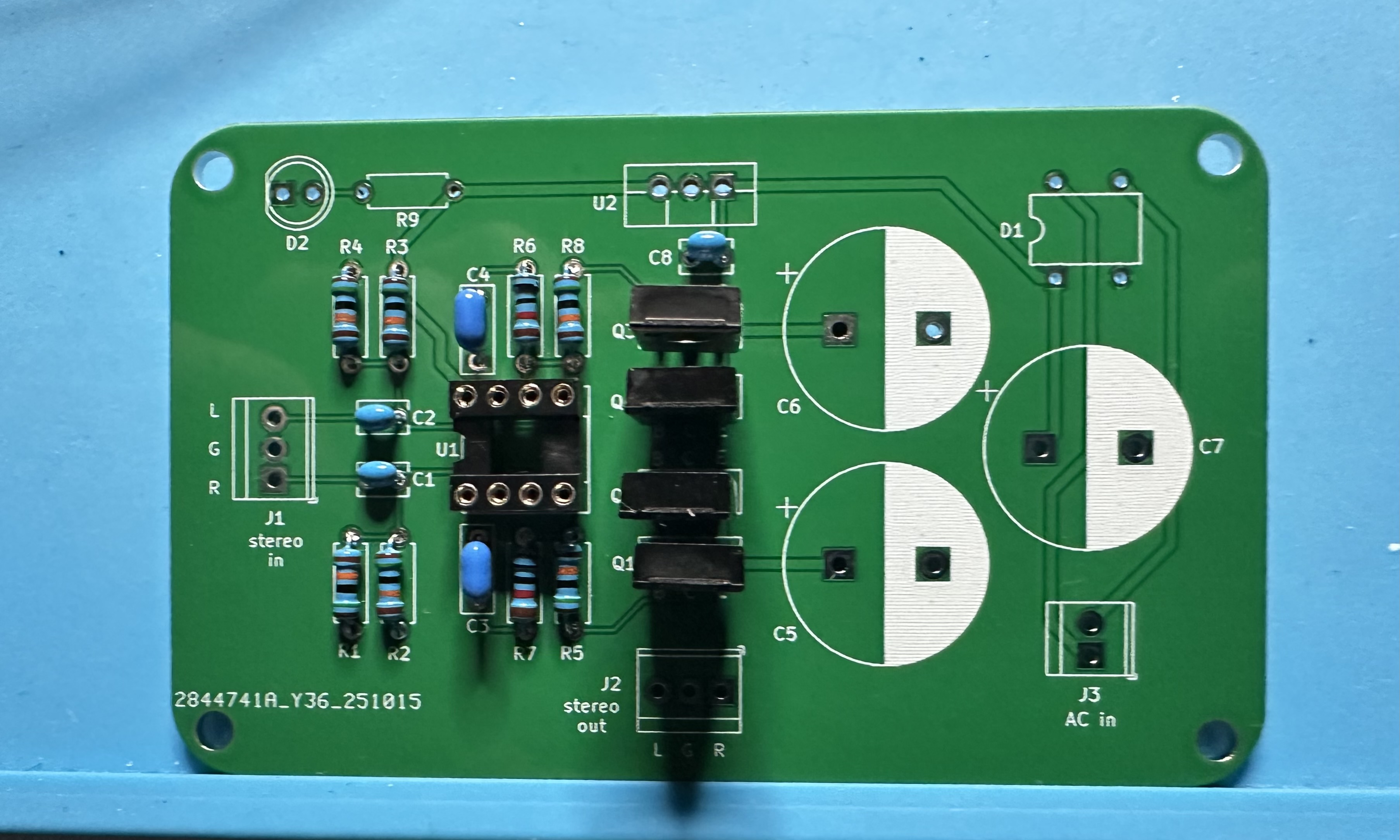
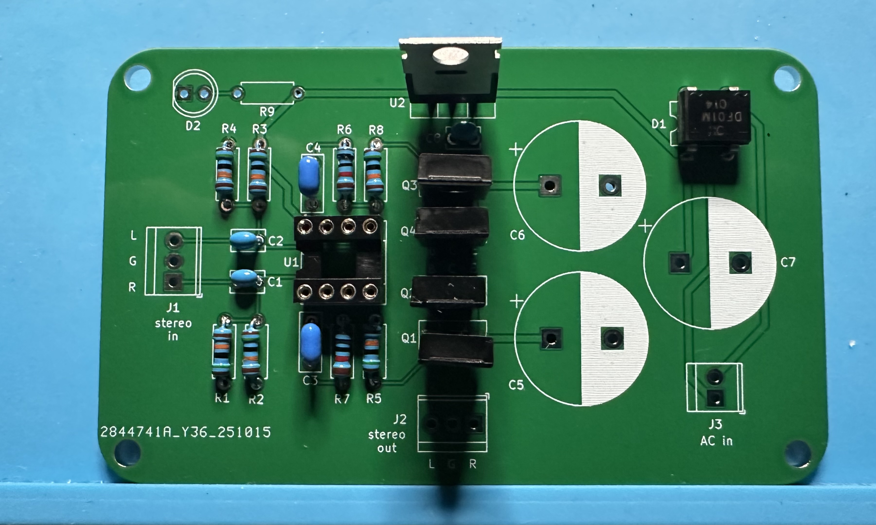
- Start small. Solder in the three 0.33-µF capacitors, C1 and C2 (for the audio inputs) and C8 (for the voltage regulator).
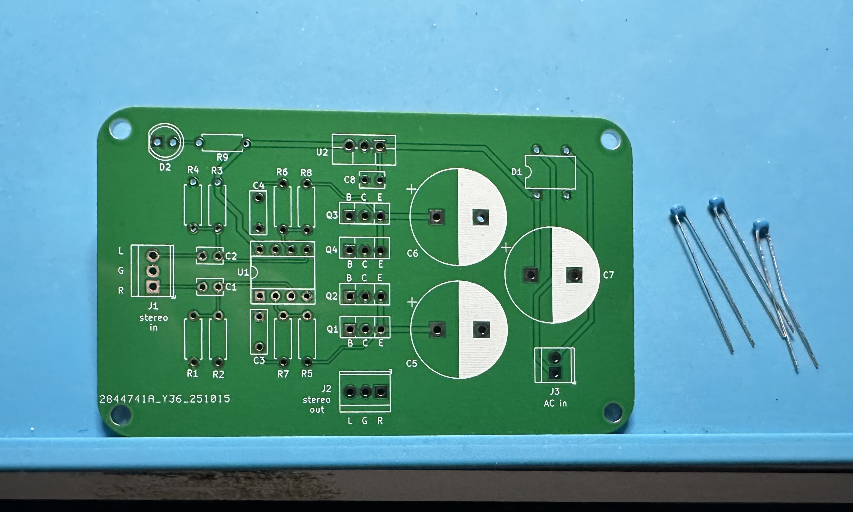
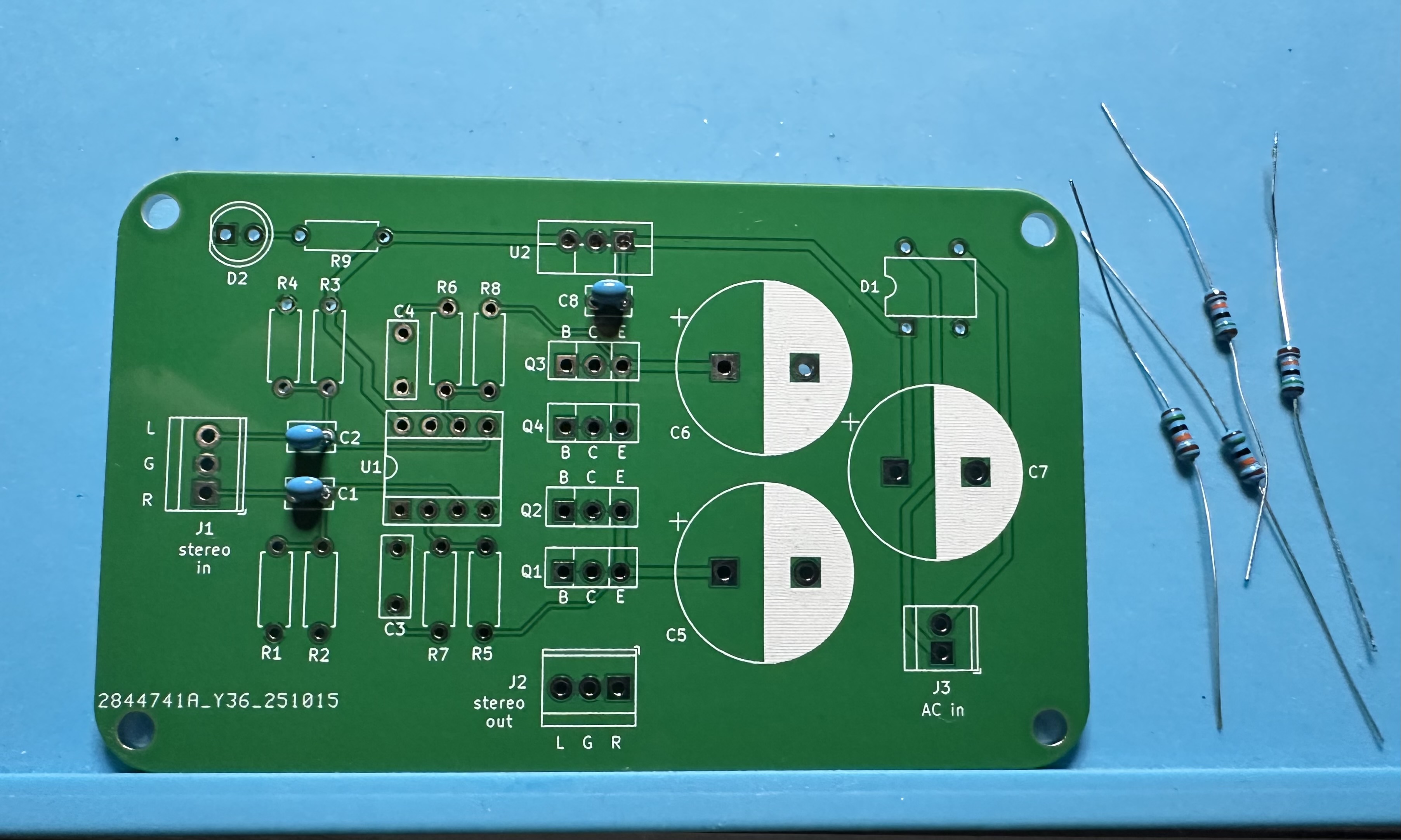
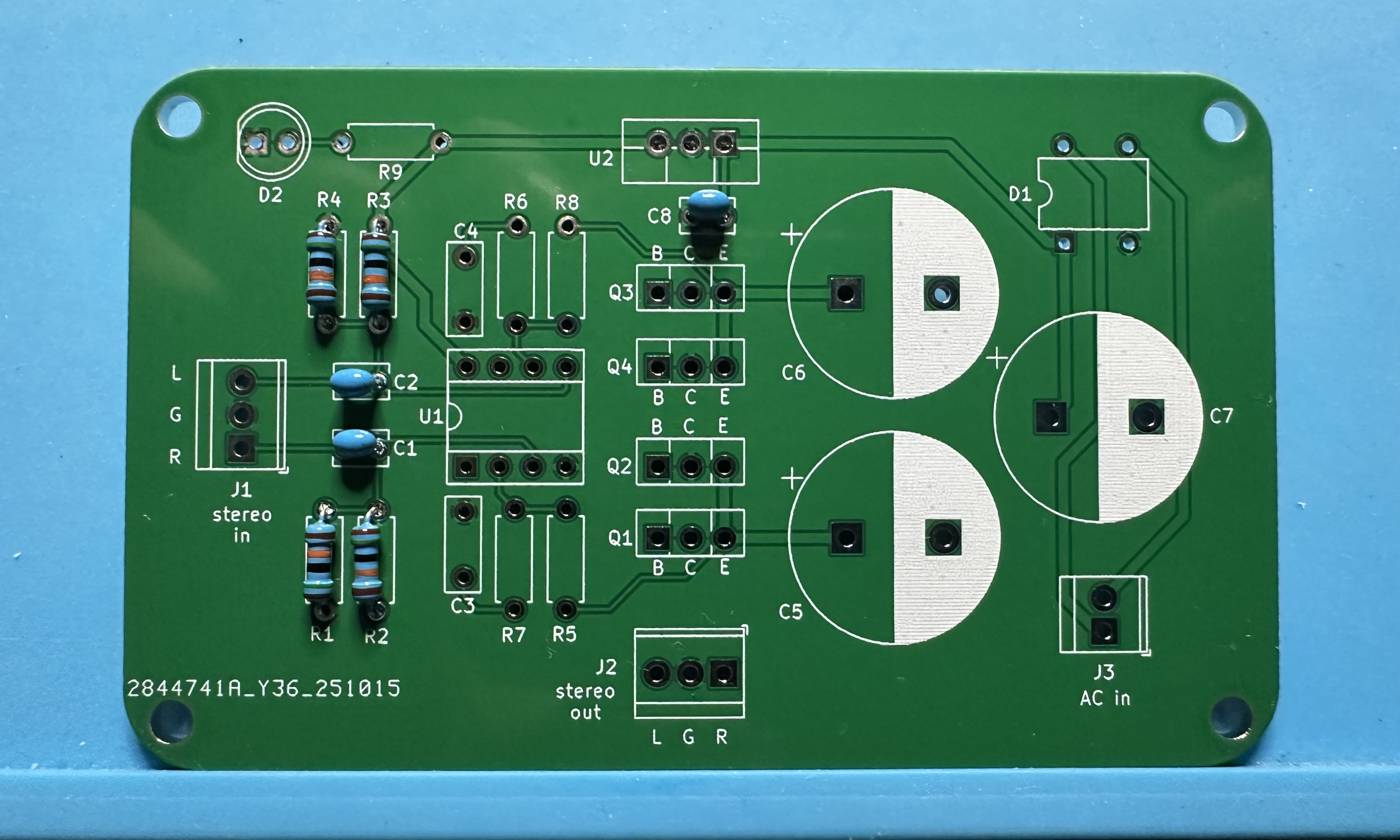
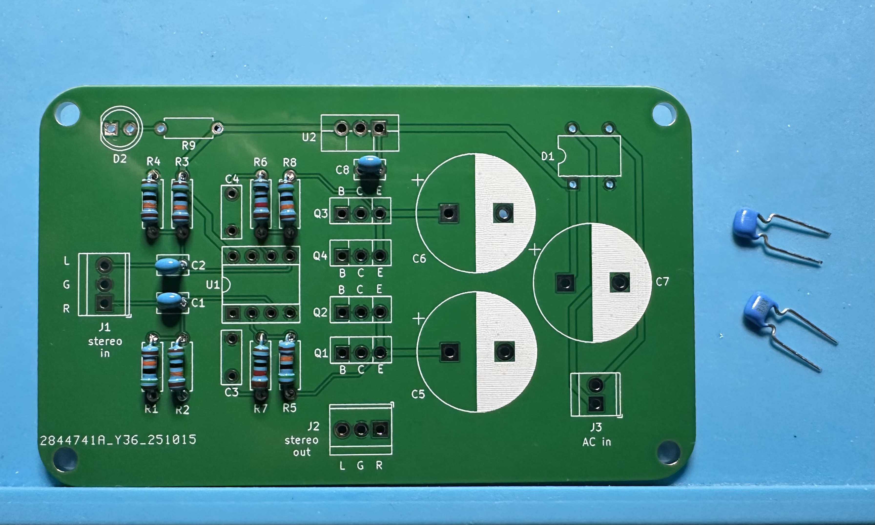
- Four 150-kΩ resistors that bias the op-amp at half the power-supply voltage, R1 – R4.
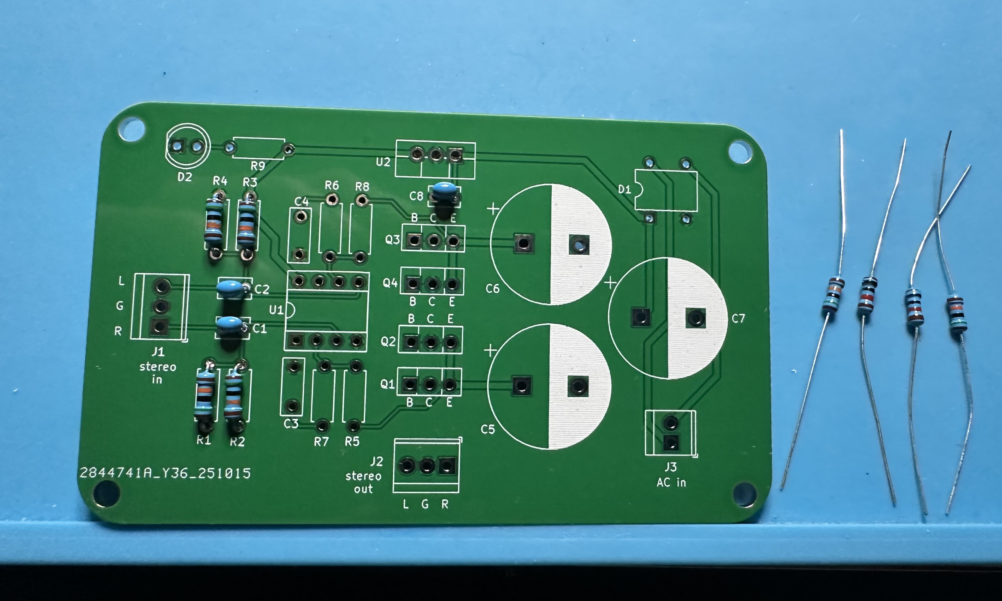
- Four more resistors for the feedback networks for the two non-inverting amps. Be careful here, R5 and R8 are 150-kΩ resistors; R6 and R7 are 10-kΩ resistors. Don't mix them up!
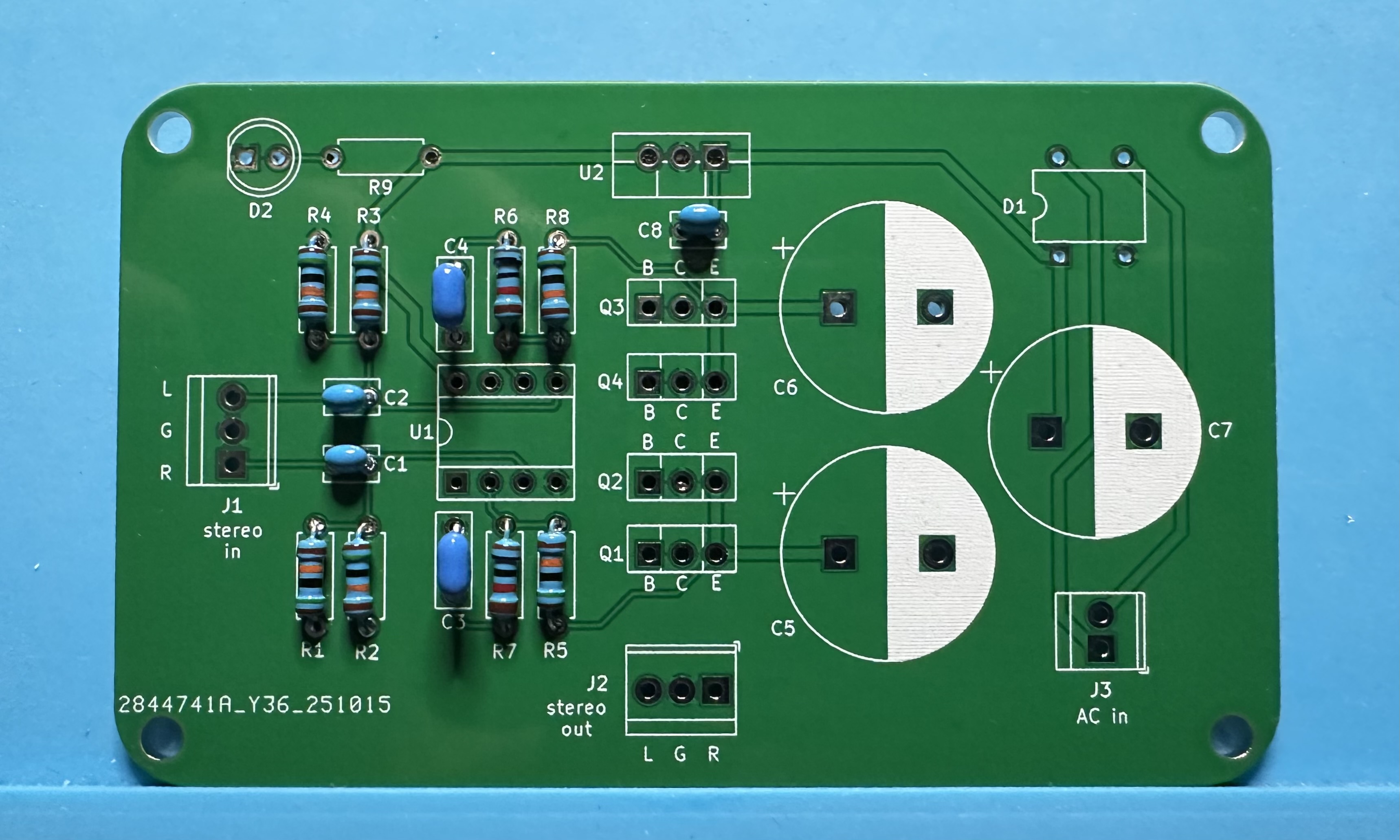
- Next, two 3.3-µF capacitors, C3 and C4, also for the feedback networks.
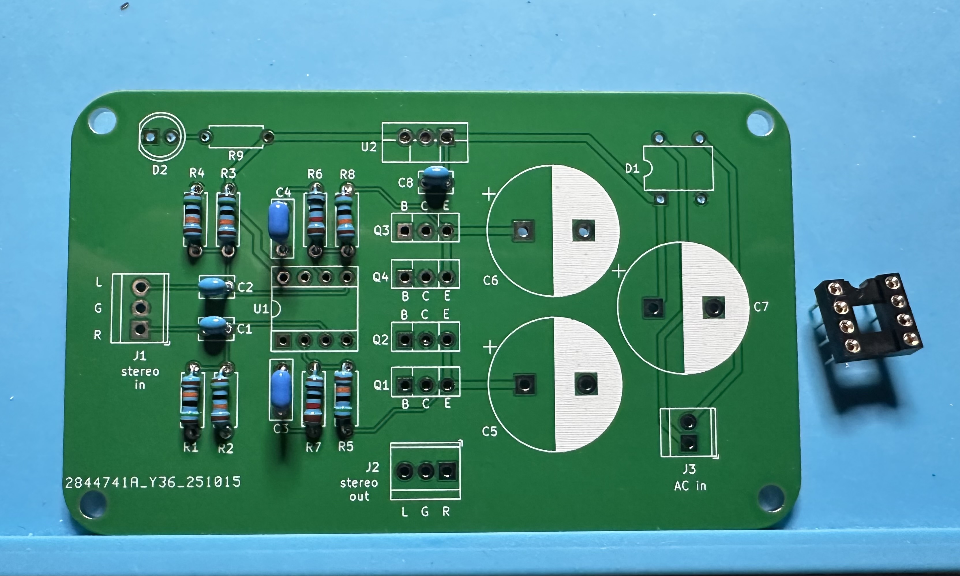
- This is as good a time as any to solder in the socket for the dual op-amp chip.
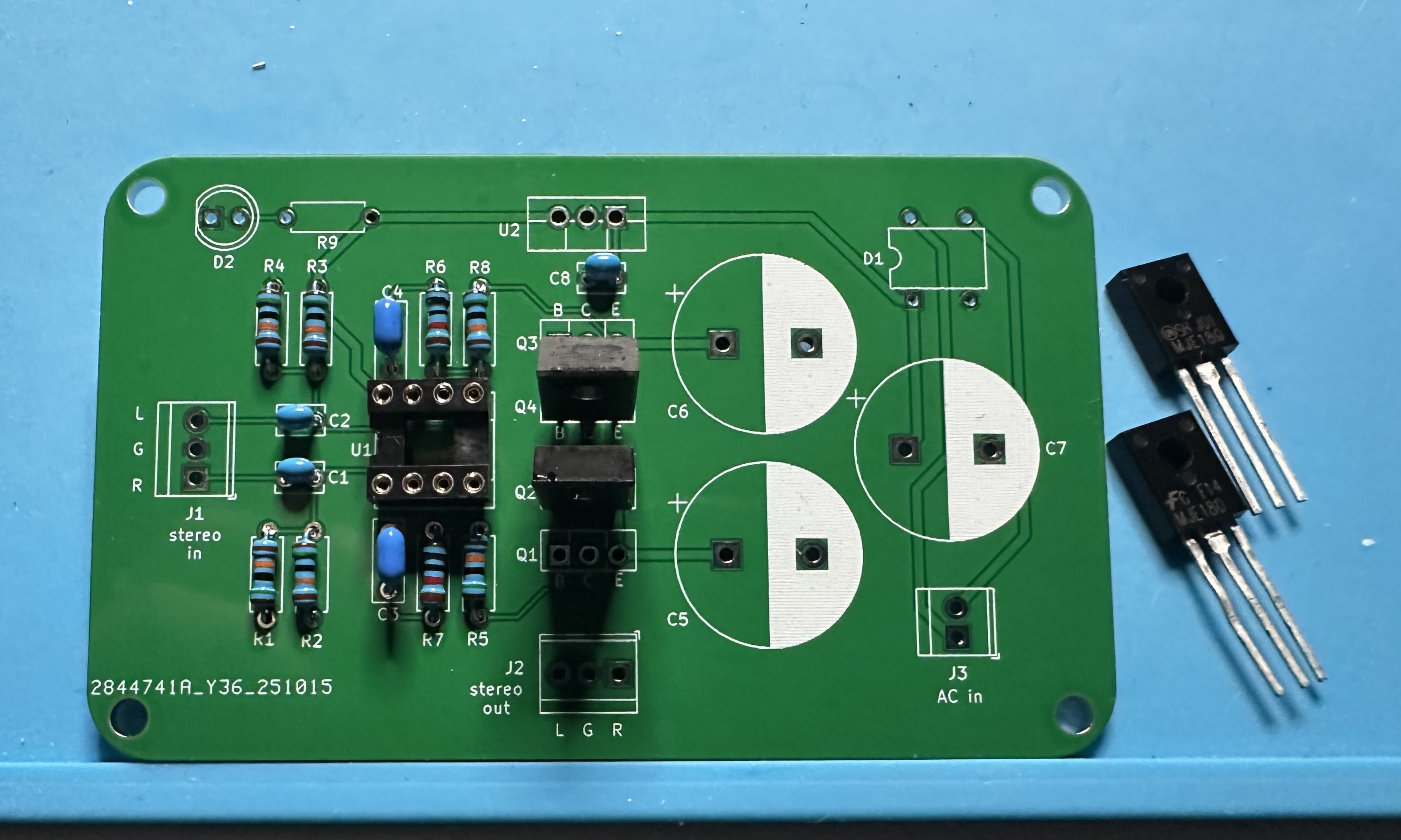
- The four BJT transistors are the trickiest part. Start with the two pnp transistors (MJE172) — Q2 and Q4 on the board. The "front" of the transistor package has labels printed on it and there are three dots arranged in a triangle. When viewed from the front, the leads, from left to right, are base (B), collector (C), and emitter (E). When inserting the transistor into the board, ensure that the leads match the labels. If you are not certain, don’t hesitate to ask for help. Mixing up the transistors can be very bad.
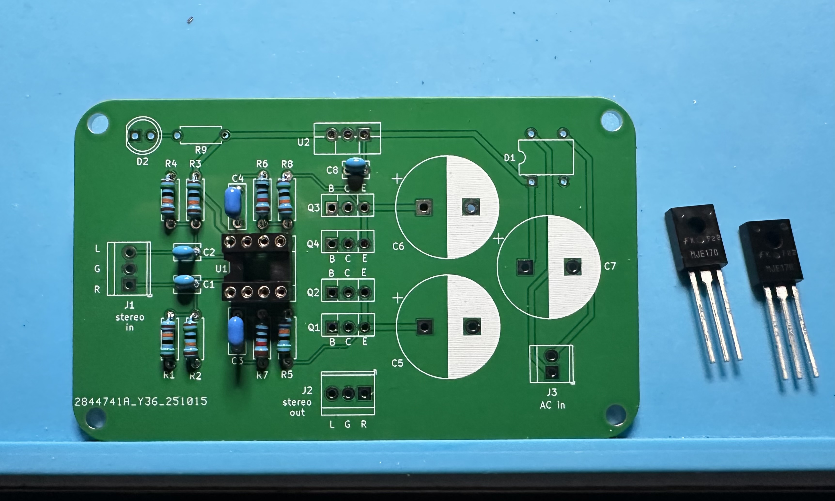
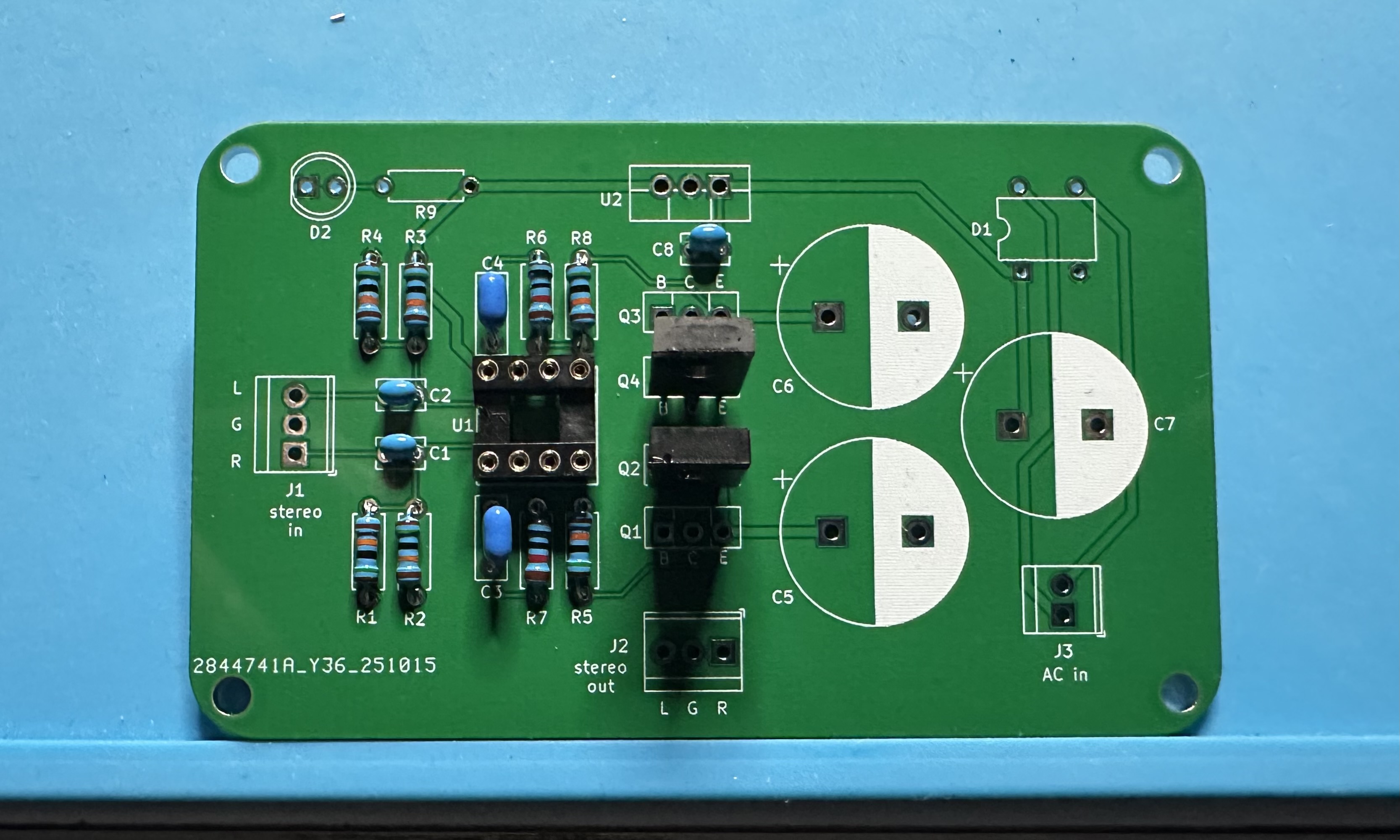
- Now add the two npn transistors (MJE182) — Q1 and Q3 on the board. The lead arrangement for the npn transistors is exactly the same as for the pnp in the previous step.
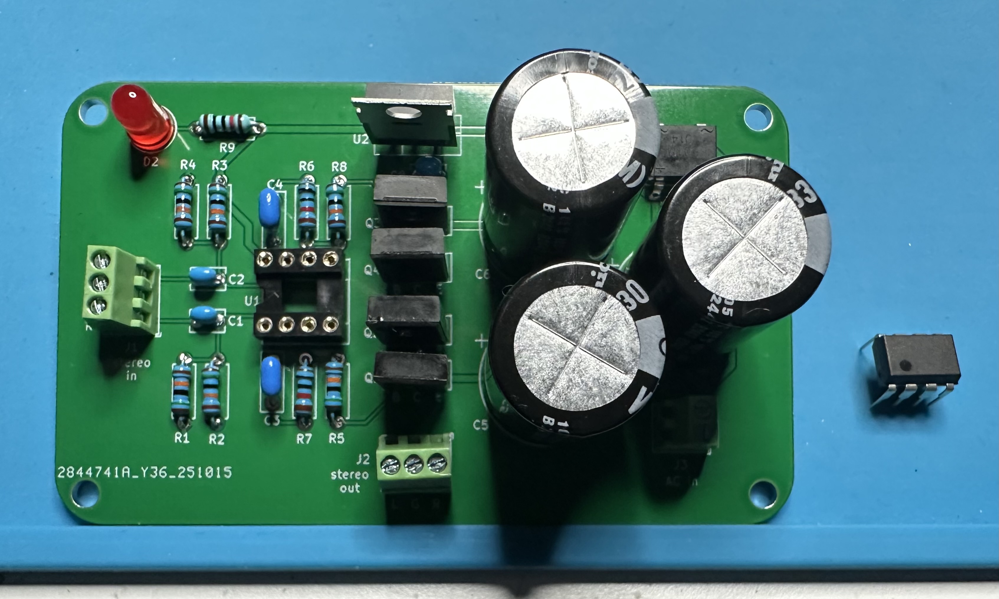
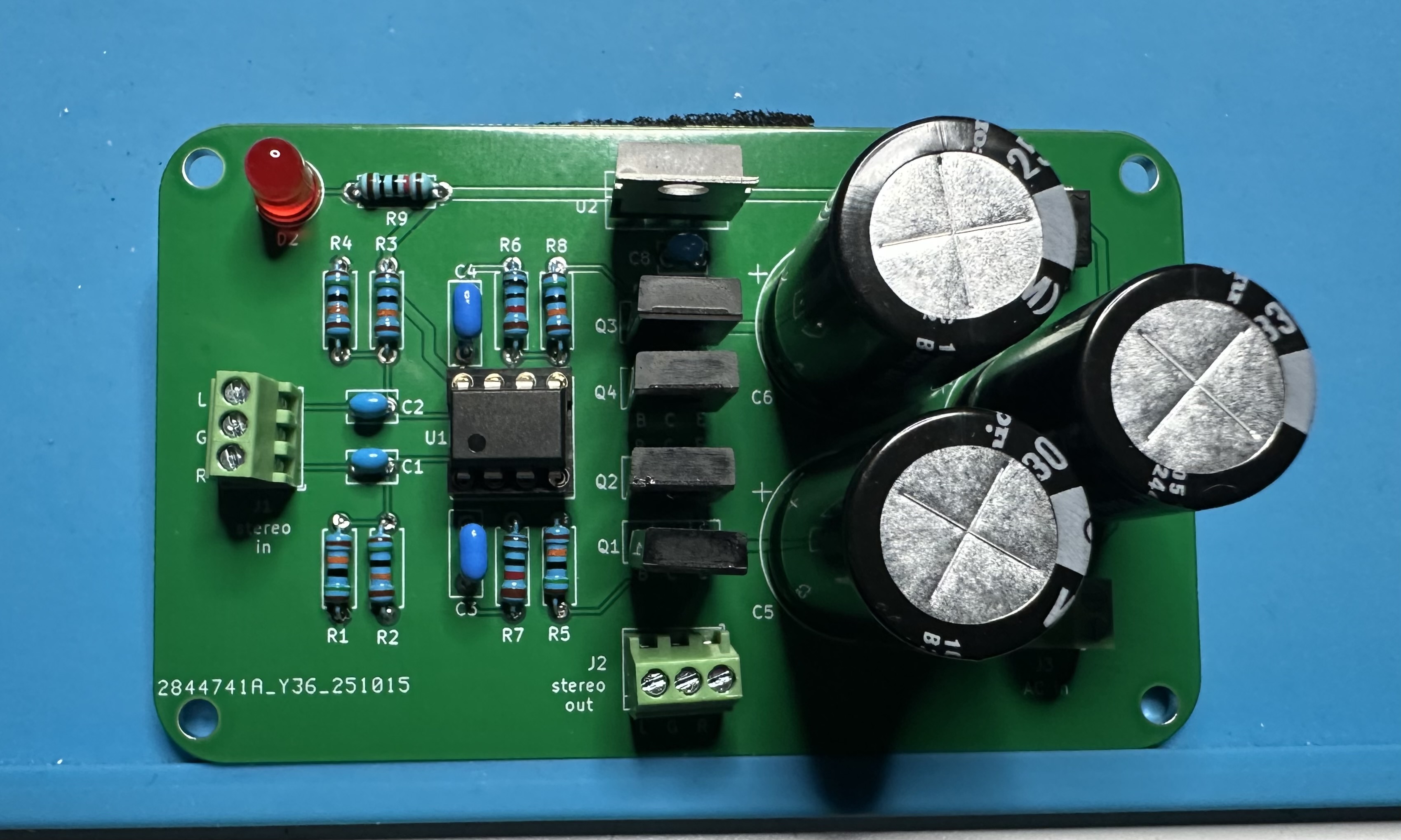
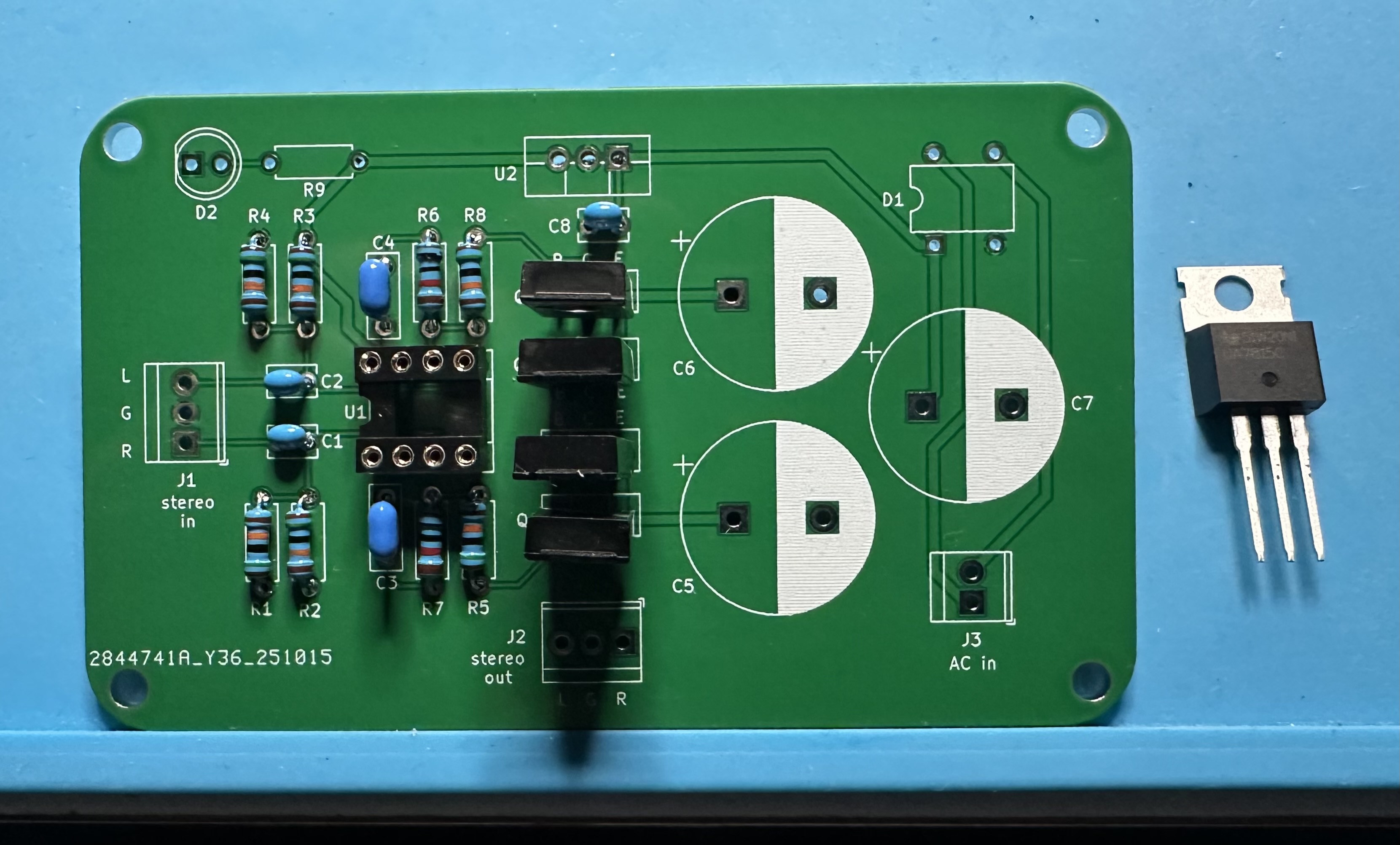
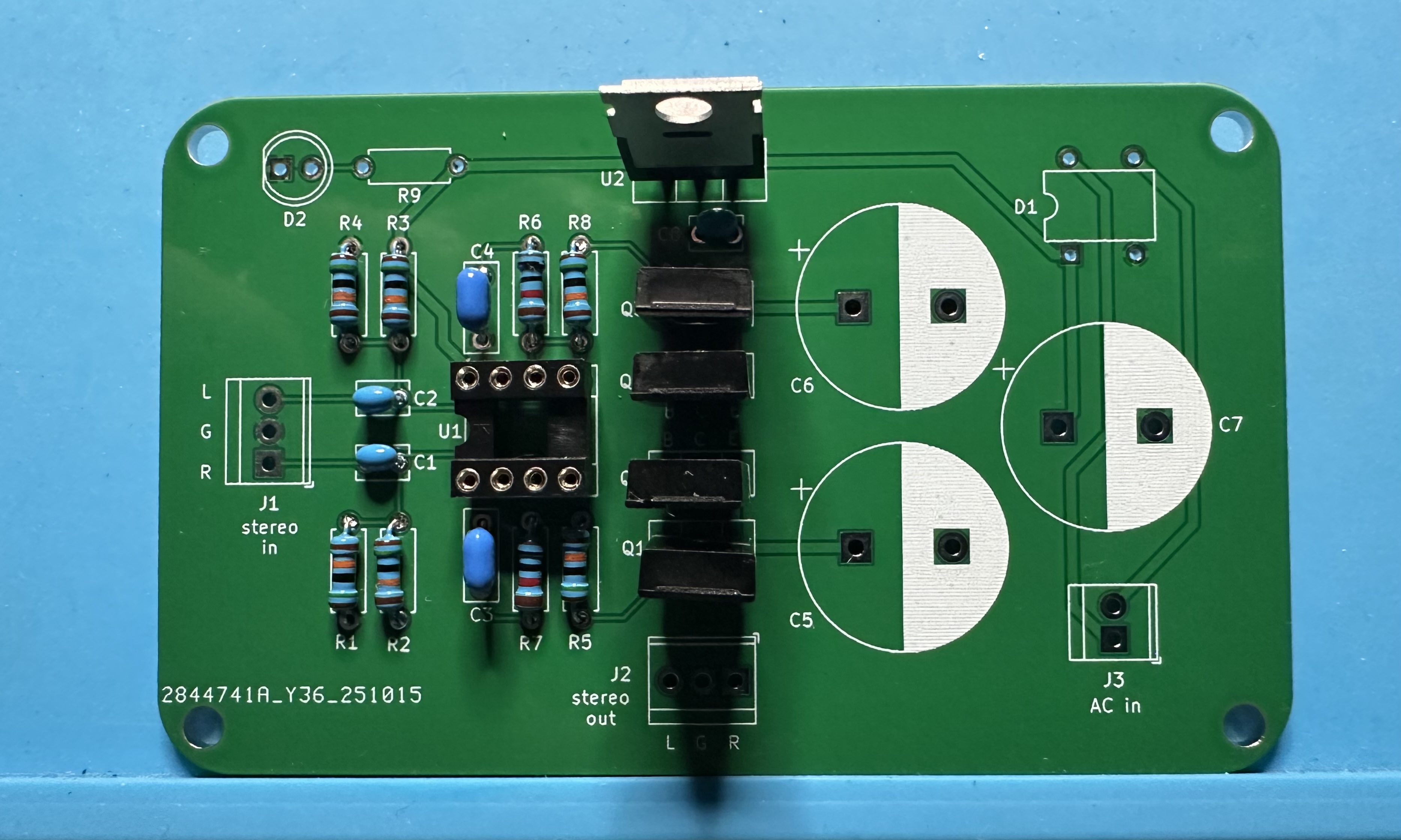
- Add the 15-V regulator (7815). When looking at the front (the side with the labels), the input lead is on the left, the output lead is on the right, and ground is in the center. The input lead should be positioned on the same side as the input capacitor, C8, which was previously installed. The front of the regulator should be oriented “looking outward” from the board, with the metal side facing the capacitor. (See the photo below.) If you have built some of the Arduino-Club projects, you may recall that the voltage regulators were installed in a horizontal configuration. In this case, the regulator is left in vertical orientation, which is perfectly fine.
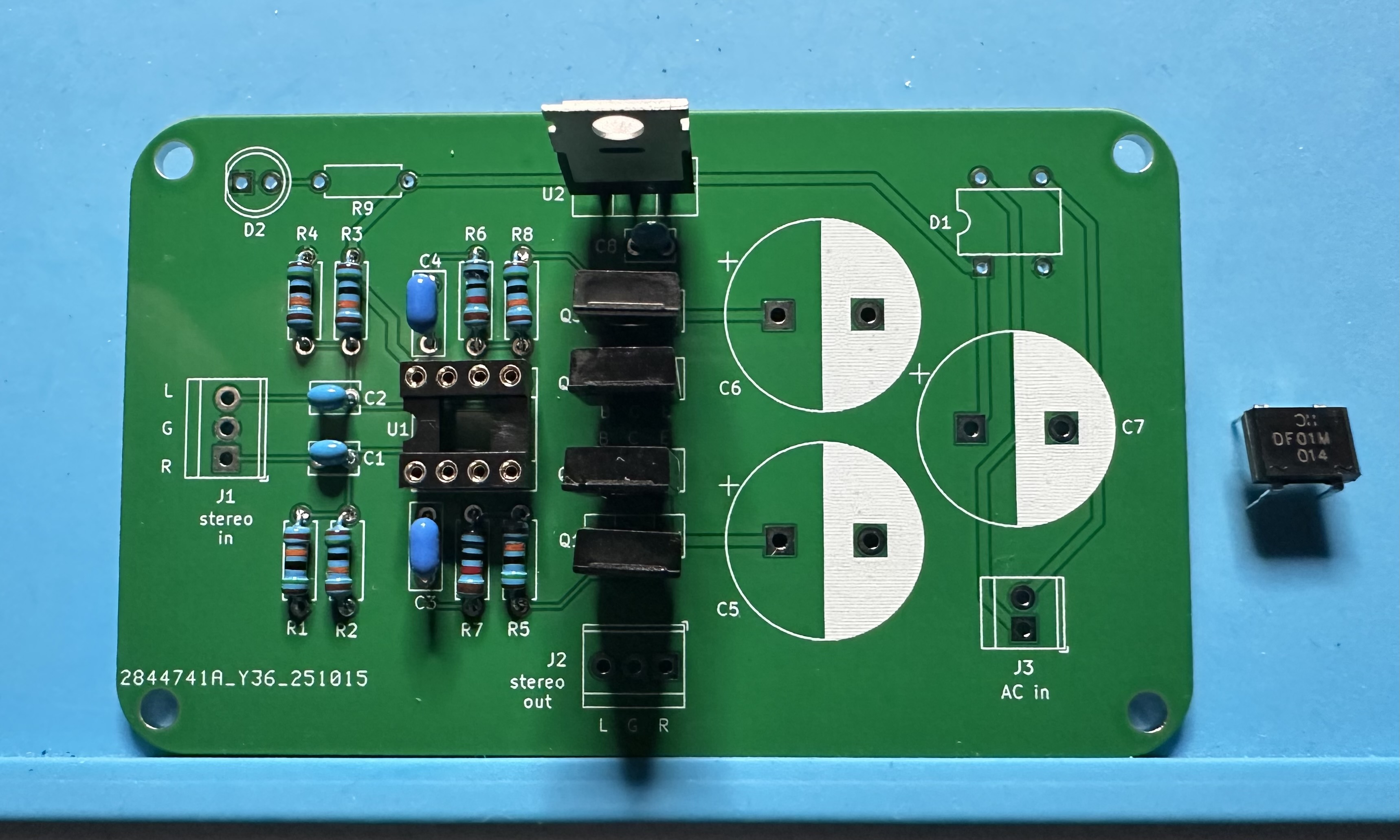
- Next, the diode rectifier bridge, DF01. If bridge in your kit does not have the "half-moon" orientation indicator, then look for labels next to the pins — the pins having a tilde (like a little sine wave) are the AC inputs and the pins with "+" and "-" are the DC outputs. The output side should be nearest to capacitor C7; the input side should be nearest the board edge.
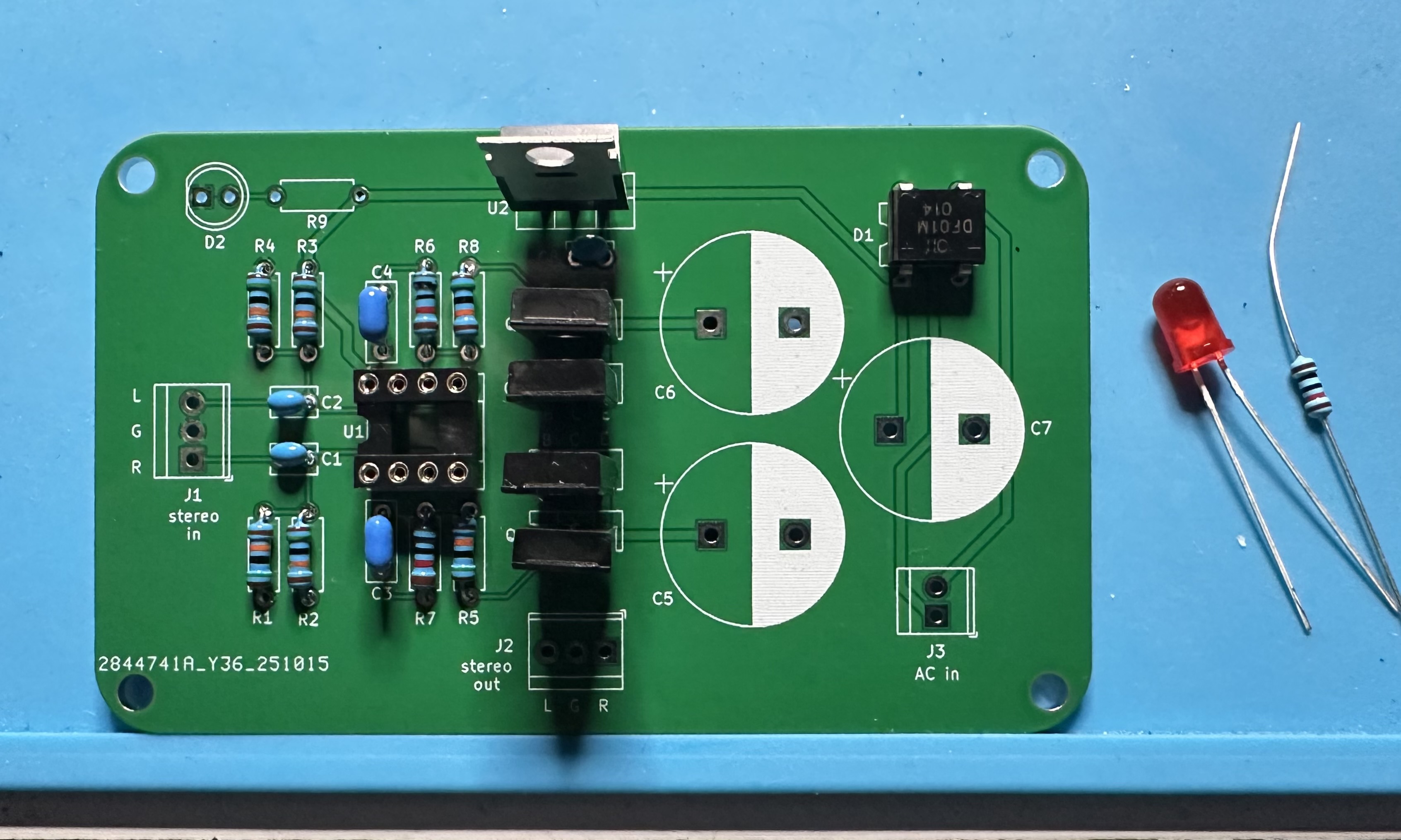
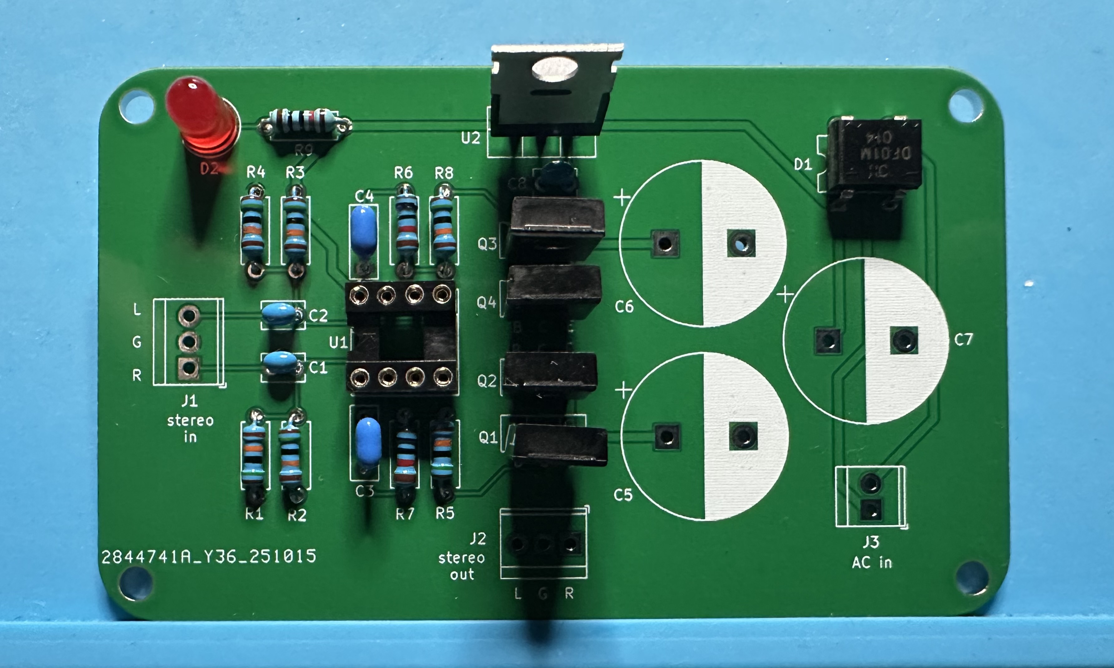
- The power indicator consists of an LED and a 10-kΩ current-limiting resistor, D2 and R9 on the board. The LED must be have the correct polarity. The longer lead is the anode (positive) and should go in the hole with the round outline; the shorter lead is the cathode (negative) and should go in the hole with the square outline. Since this is a 5-mm LED package, you can also match up the flat edge on the LED with the flat mark on the footprint.
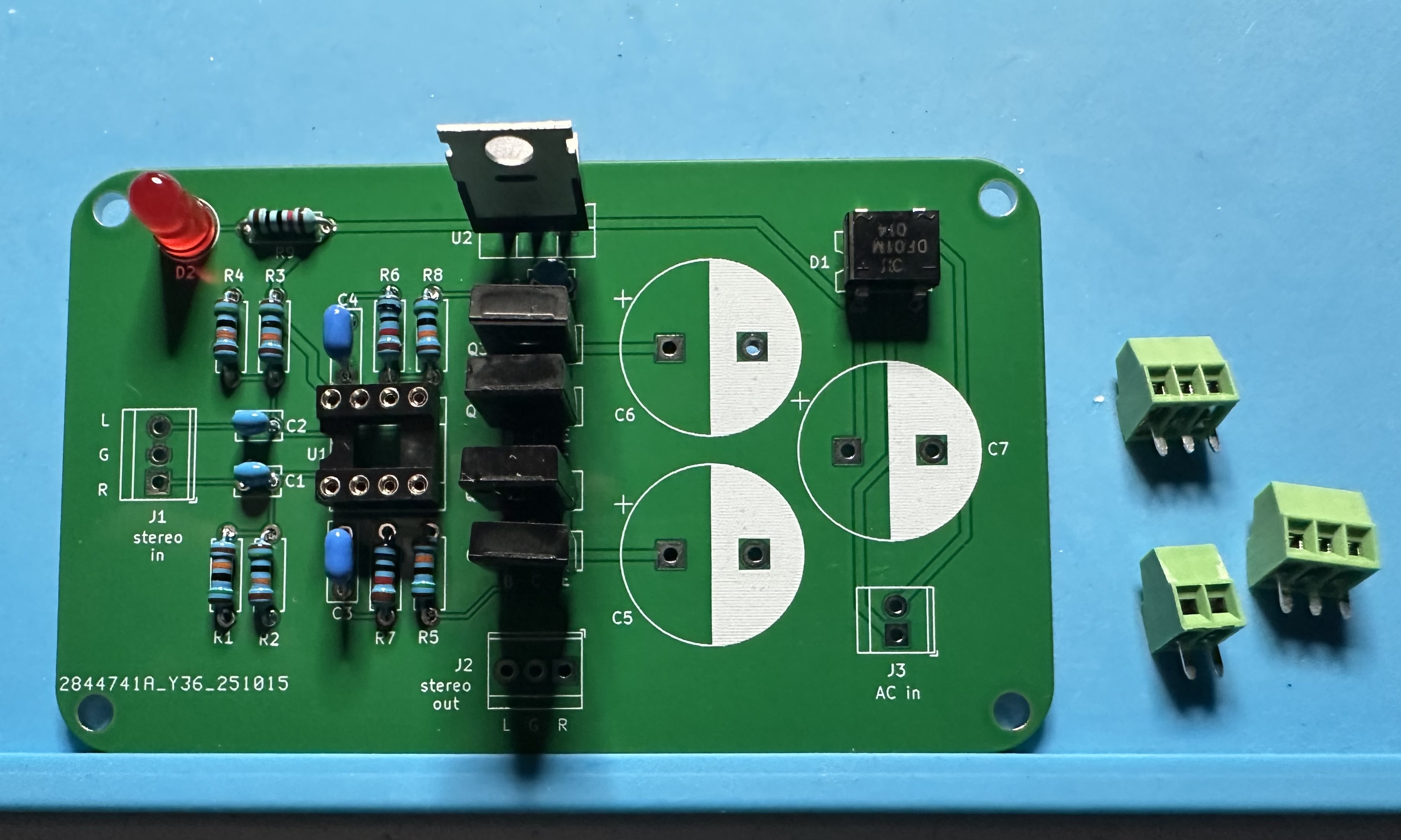
- Install the three terminal blocks — two three-position blocks for audio input and output and one two-position block for power.
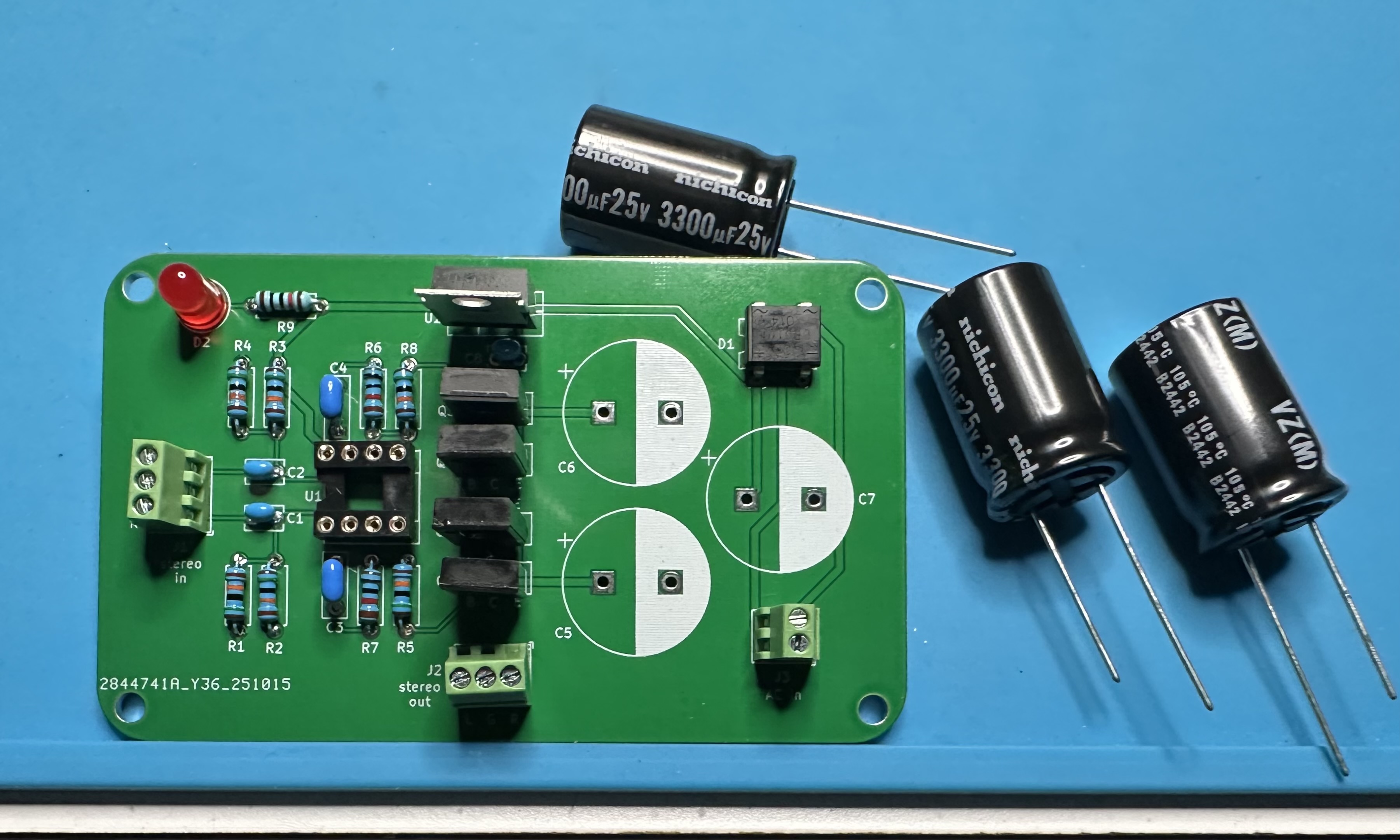
- Last bit of soldering — install the three big 3300-µF capacitors, C5-C7. These are electrolytic, so be sure to get the correct polarity.
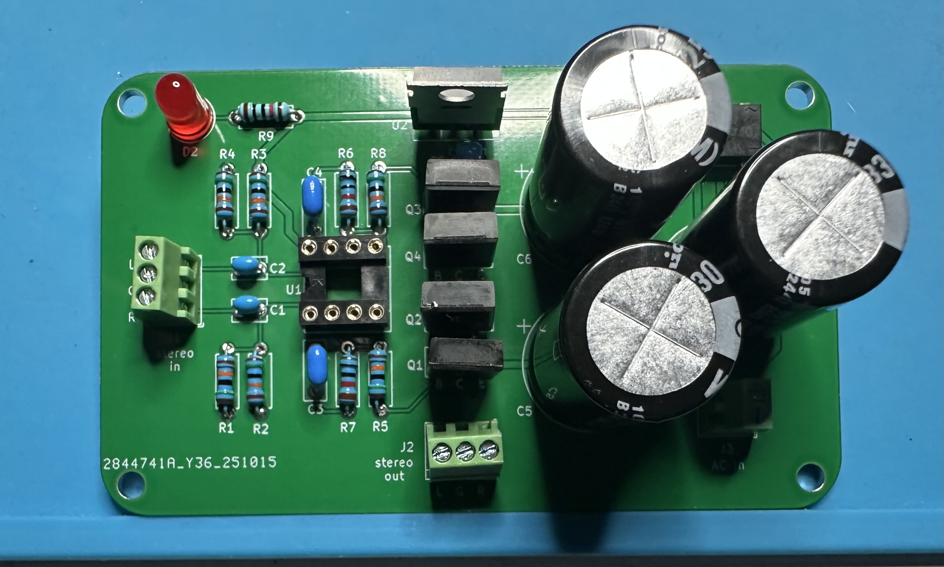
- Finally, insert the TL082 dual op-amp chip into the socket. Time to test!