ISU Audio and Arduino Club
Resistometer project build instructions
Below are step-by-step instructions for building the Resistometer project.
The order of assembly given below is a suggestion — there is nothing wrong with soldering the parts in a different order.
The usual tools are required: solder and soldering iron, needle-nosed pliers for manipulating parts and pulling leads, and wire cutters for trimming leads after soldering. Helpful but not essential would be a vise for holding the boards and a magnifying glass and light for viewing small print.
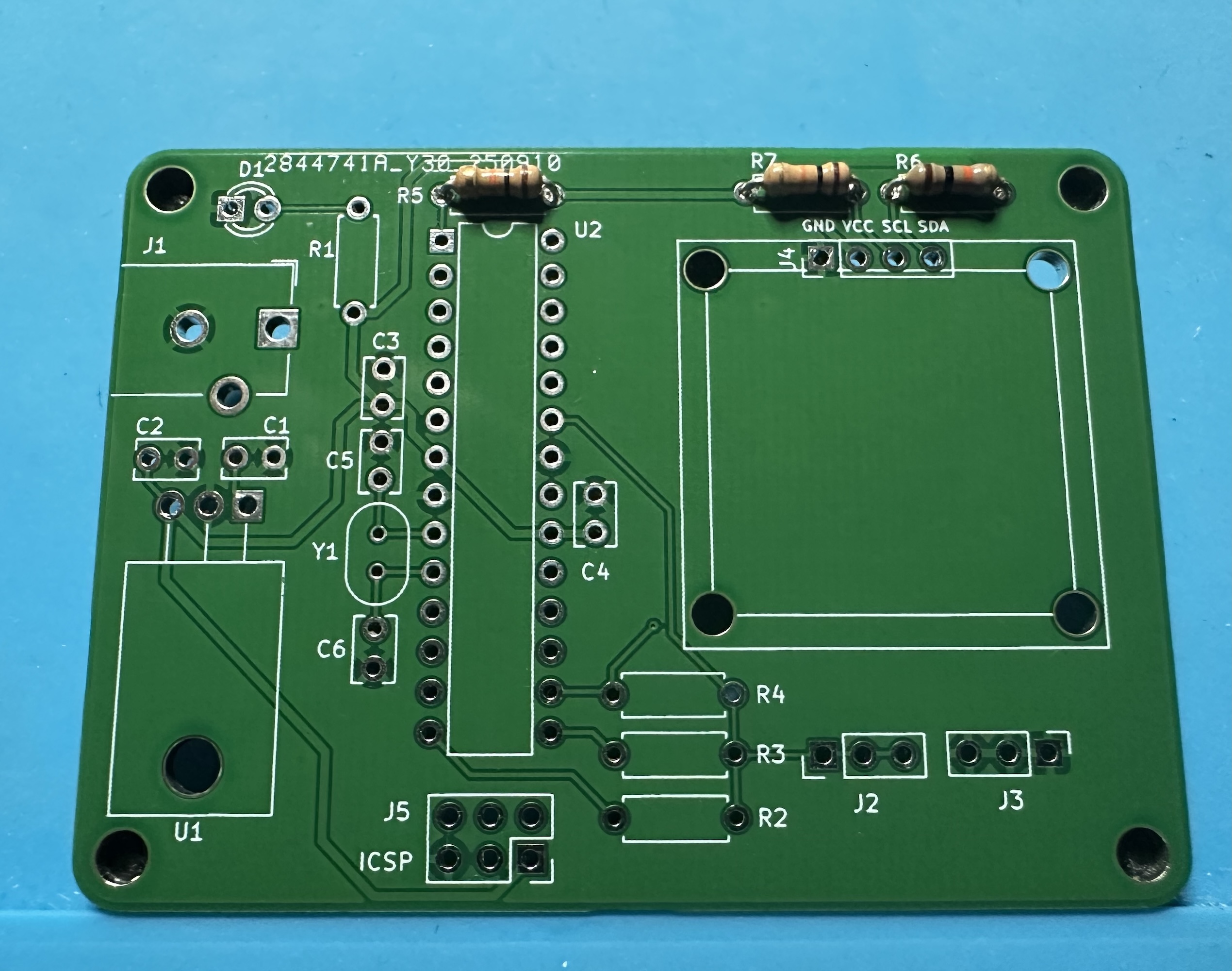
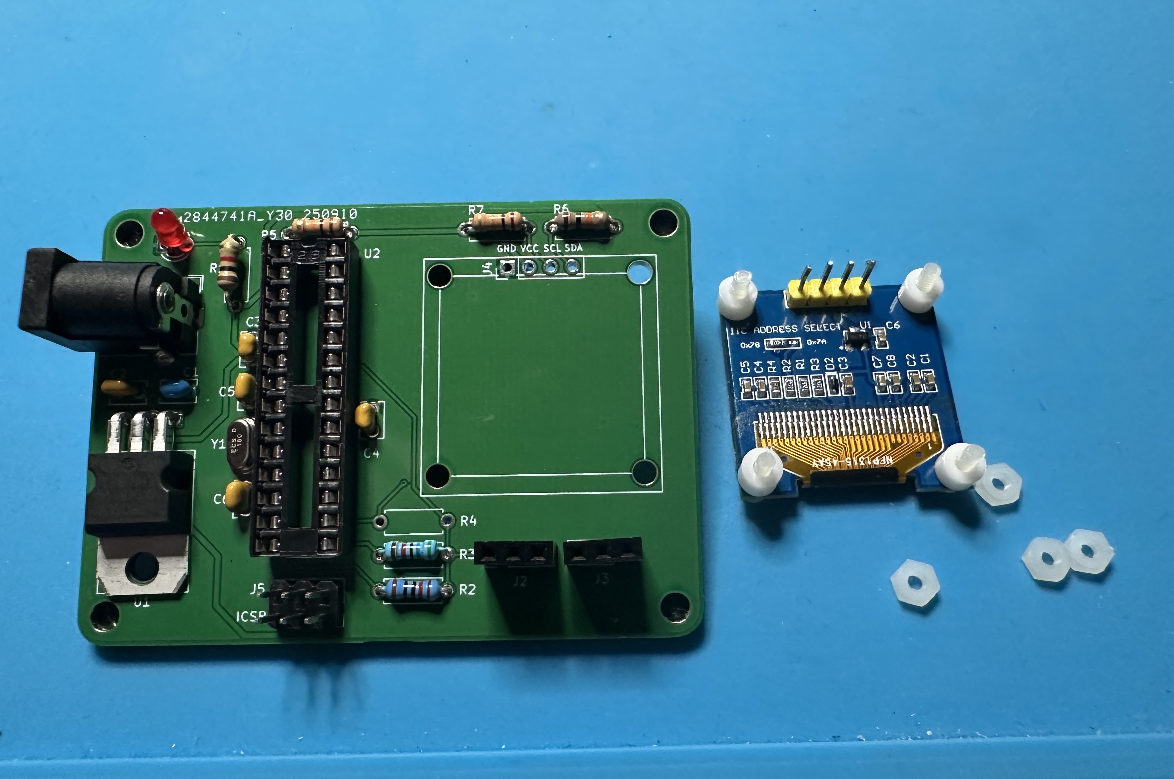
- Assemble the parts. (See the BoM for the complete list.)
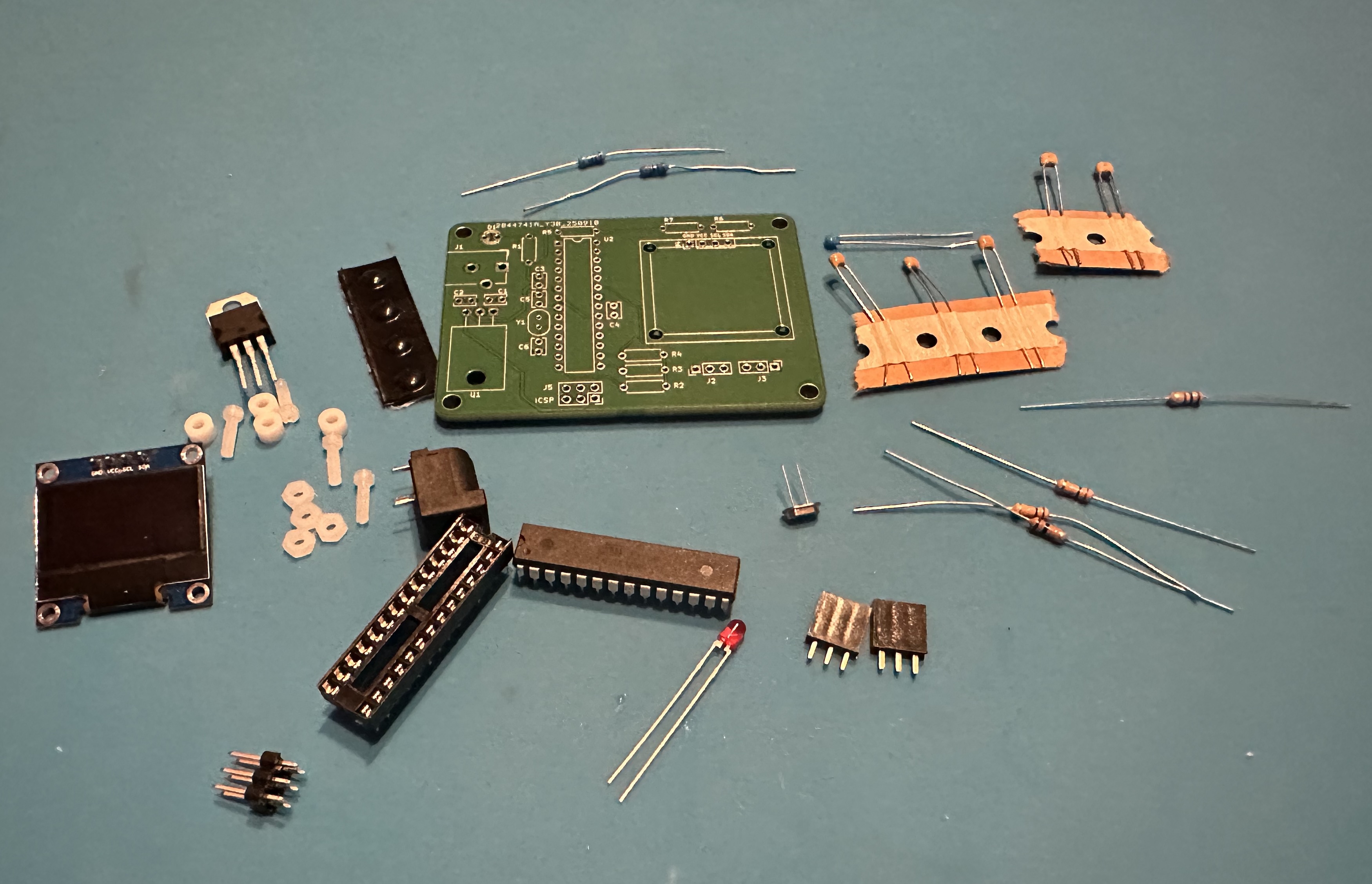
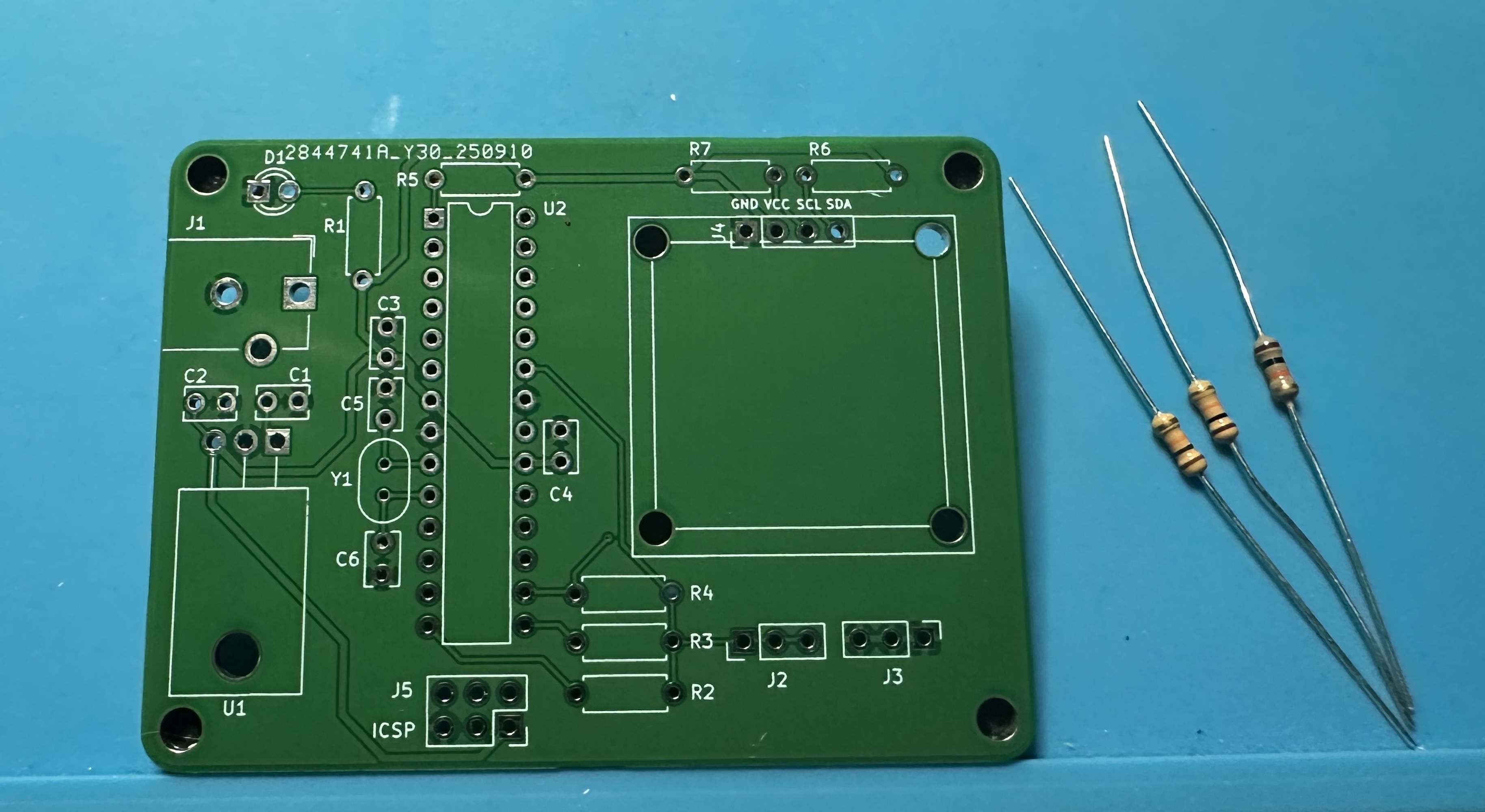
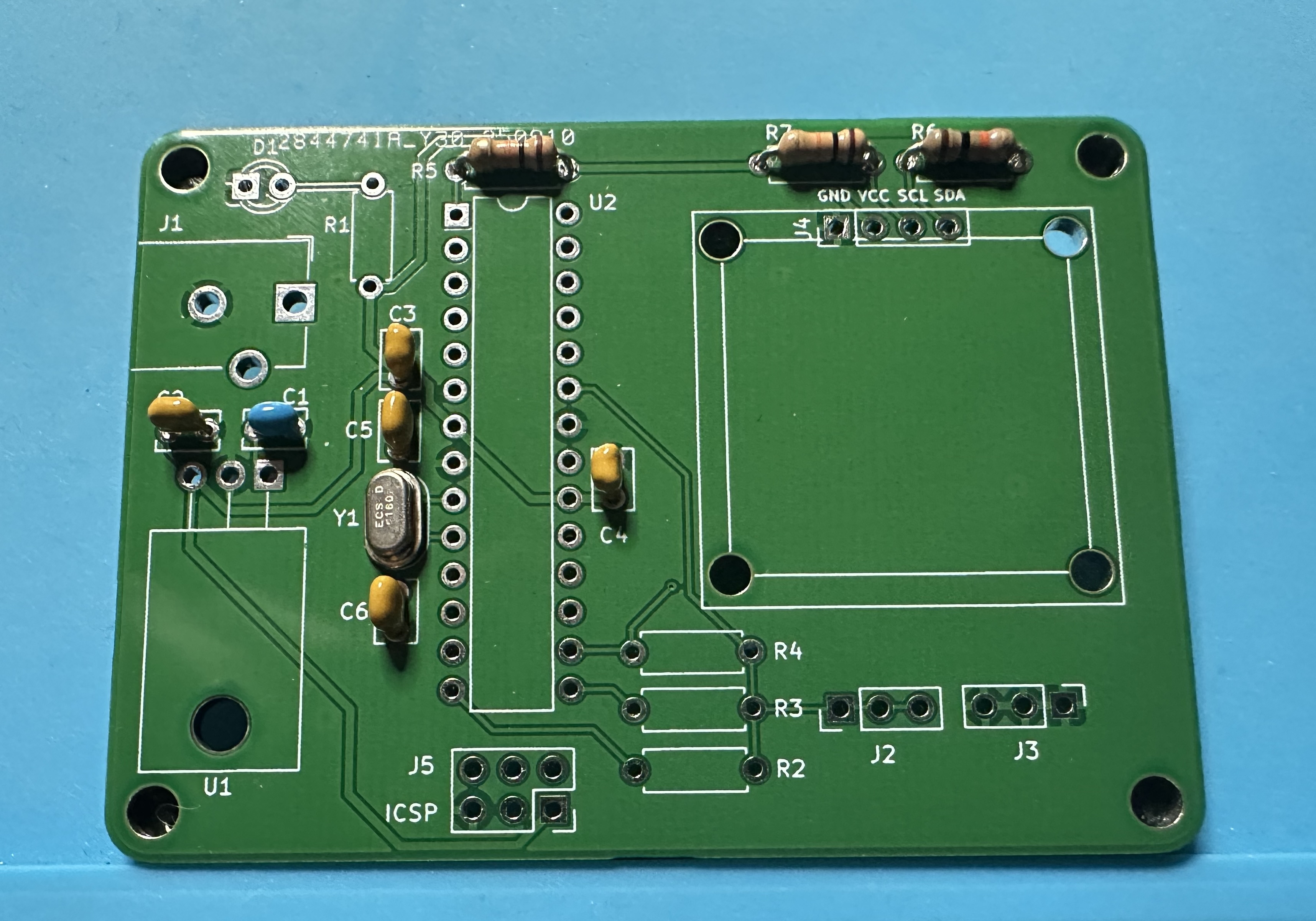
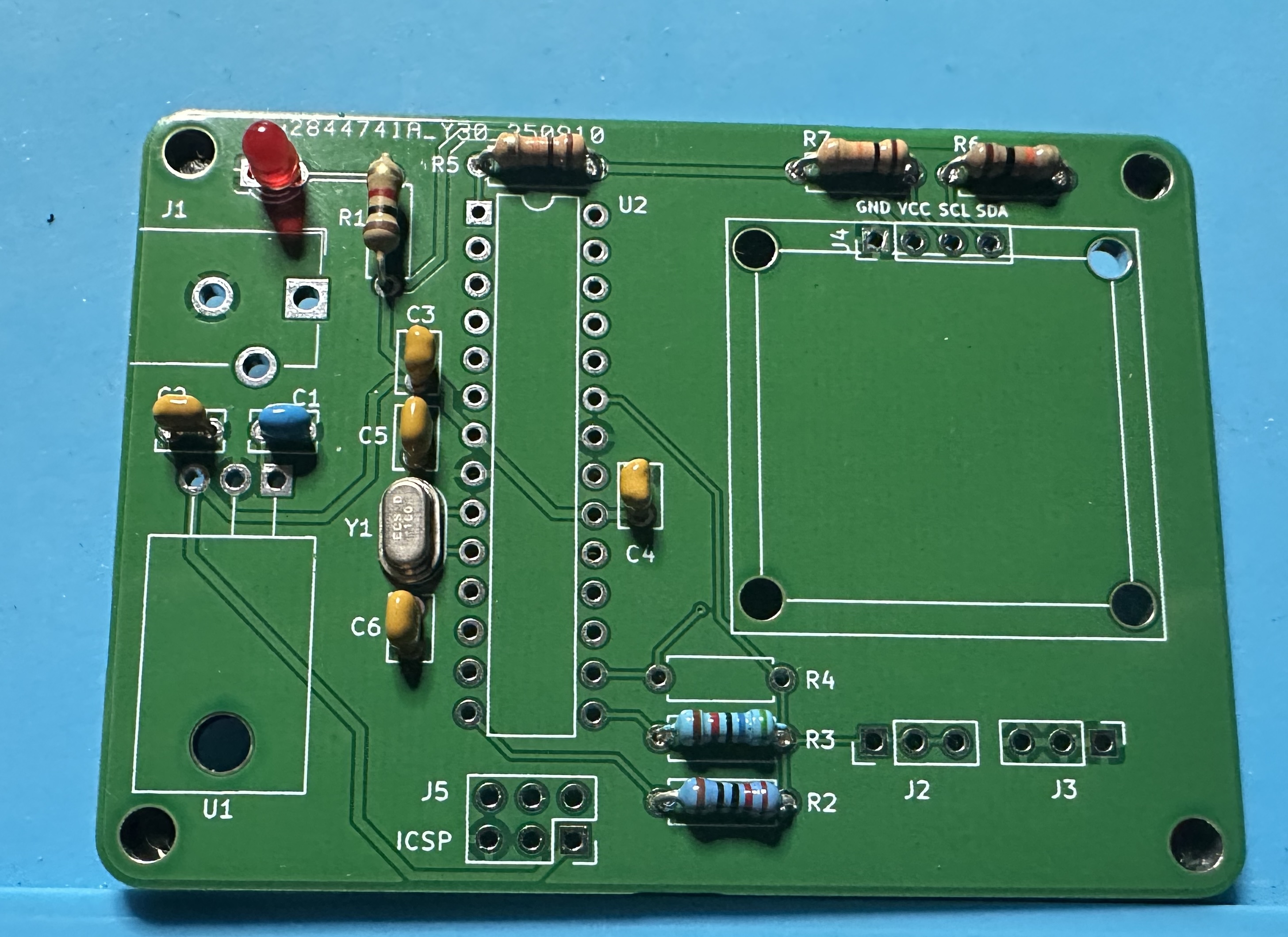
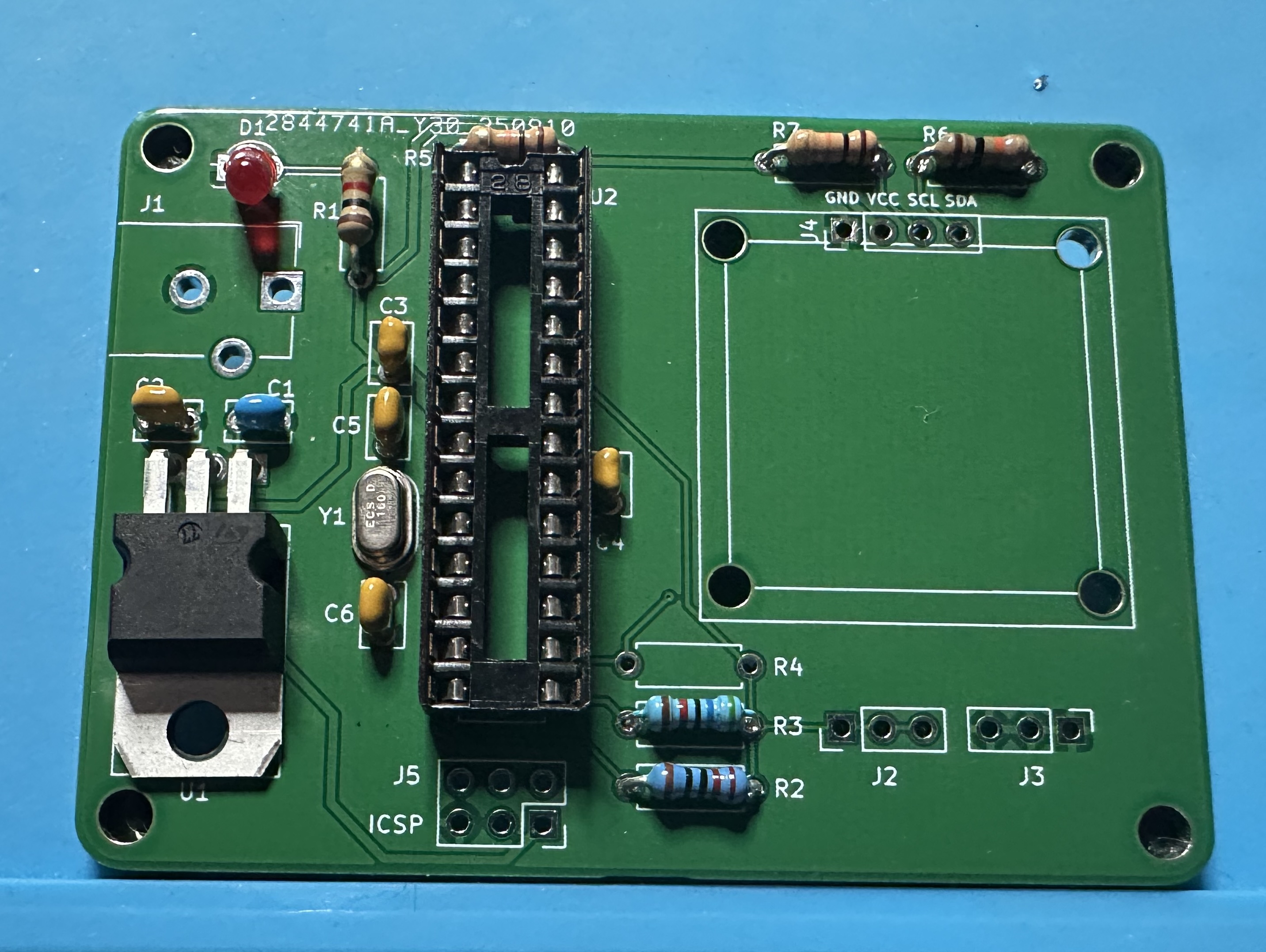
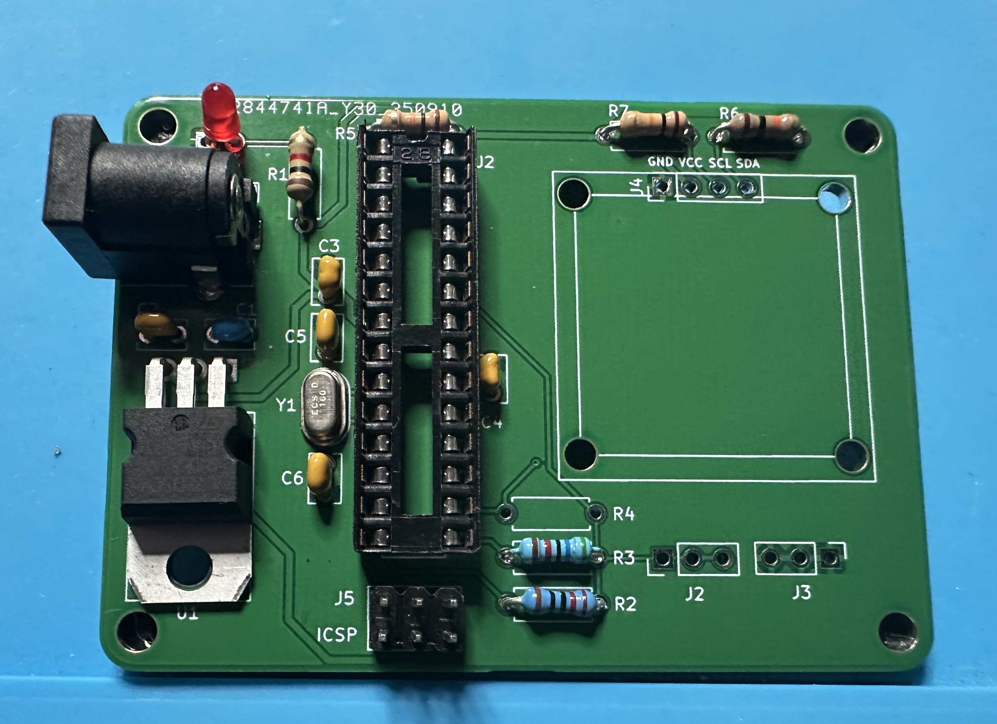
- As usual, we start small and work our way to the bigger parts. The three 10-kΩ resistors (brown-black-orange) resistors are easy to do. These are 5% tolerance resistors. Two are pullups for the I2C serial communications channel (R6 and R7) and one is the pullup for the Atmega reset (R5).
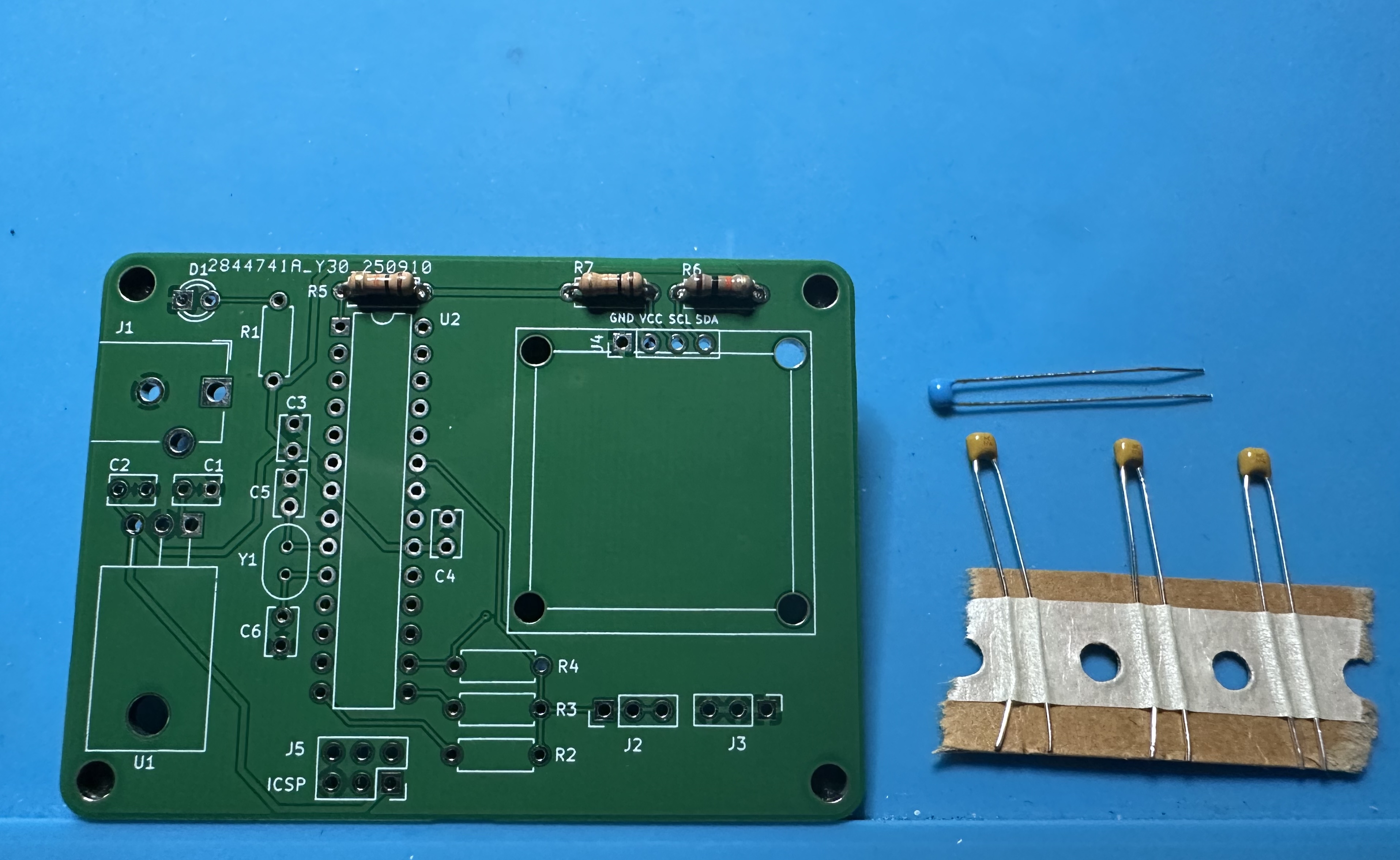
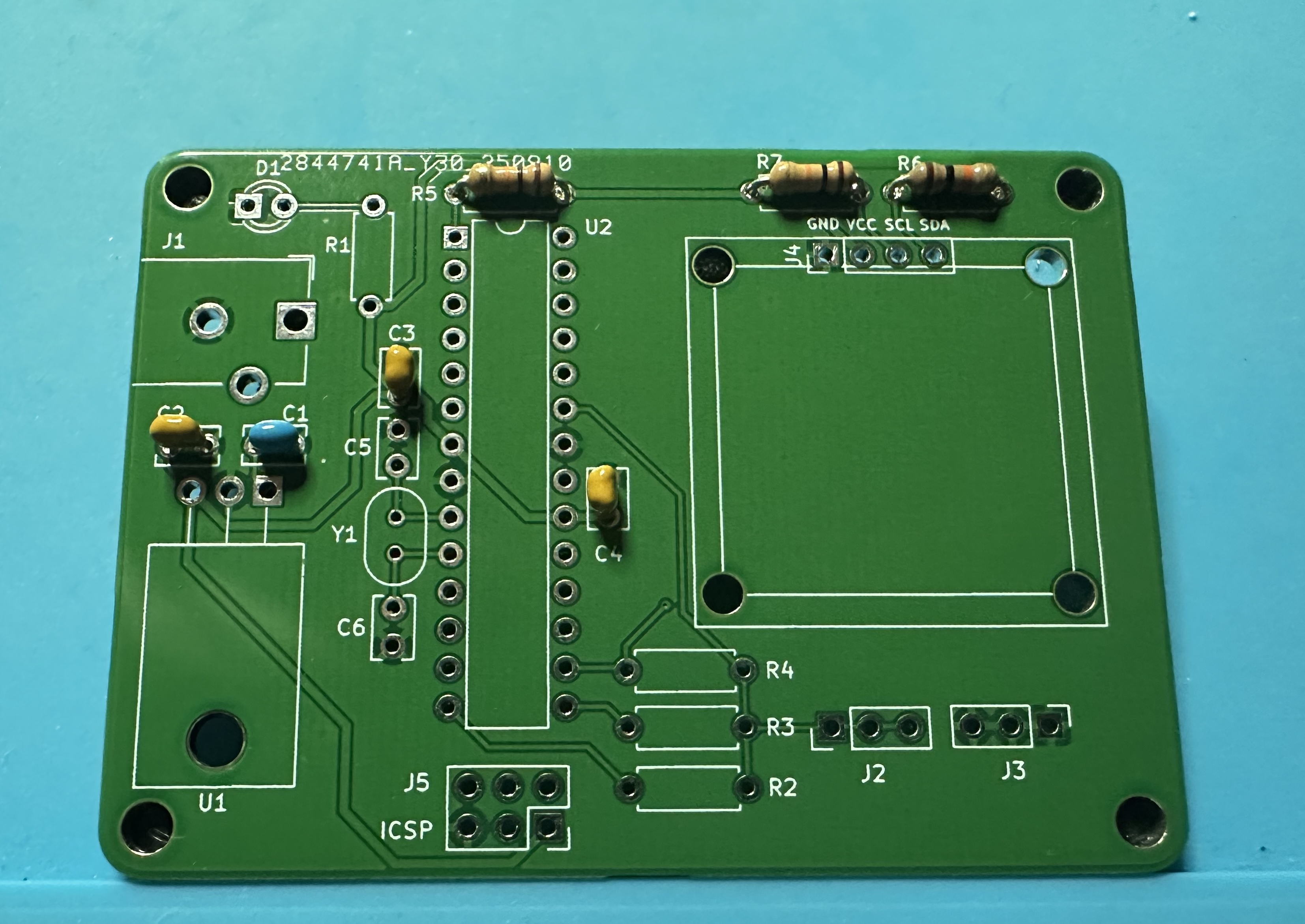
- Next, do four small capacitors. Two 100-nF (104) capacitors — 2 for Atmega bypassing (C3 and C4), one 0.22-uF (224) or 0.33-uF (334) capacitor for the input of the voltage regulator (C1), (Either works, use whatever is in your kit.), and one 100-nF capacitor on the output of the regulator.(C2).
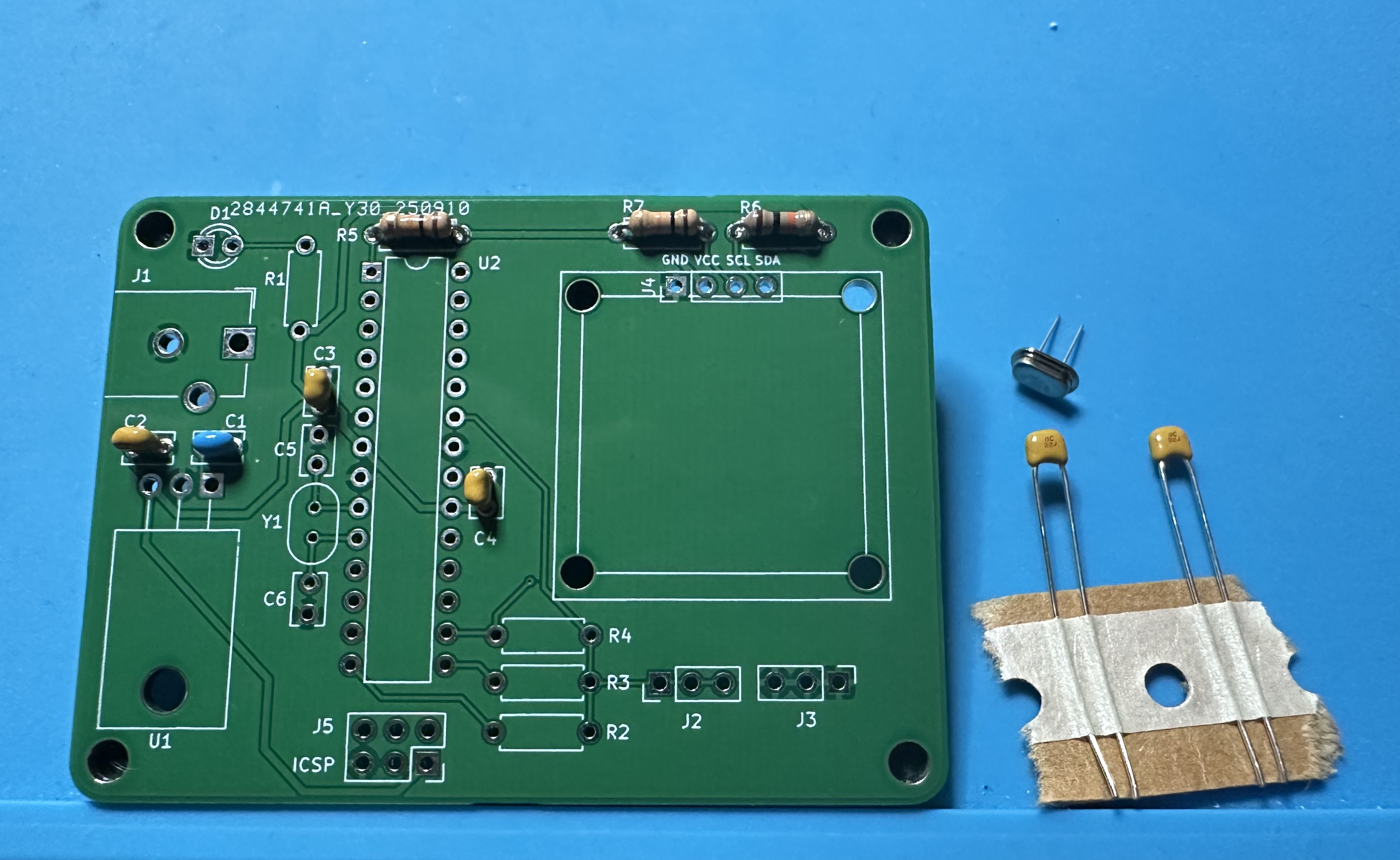
- Now, let's do the 16-MHz oscillator crystal (Y1) for the microcontroller and associated 22-pF (22J) capacitors (C5 and C6).
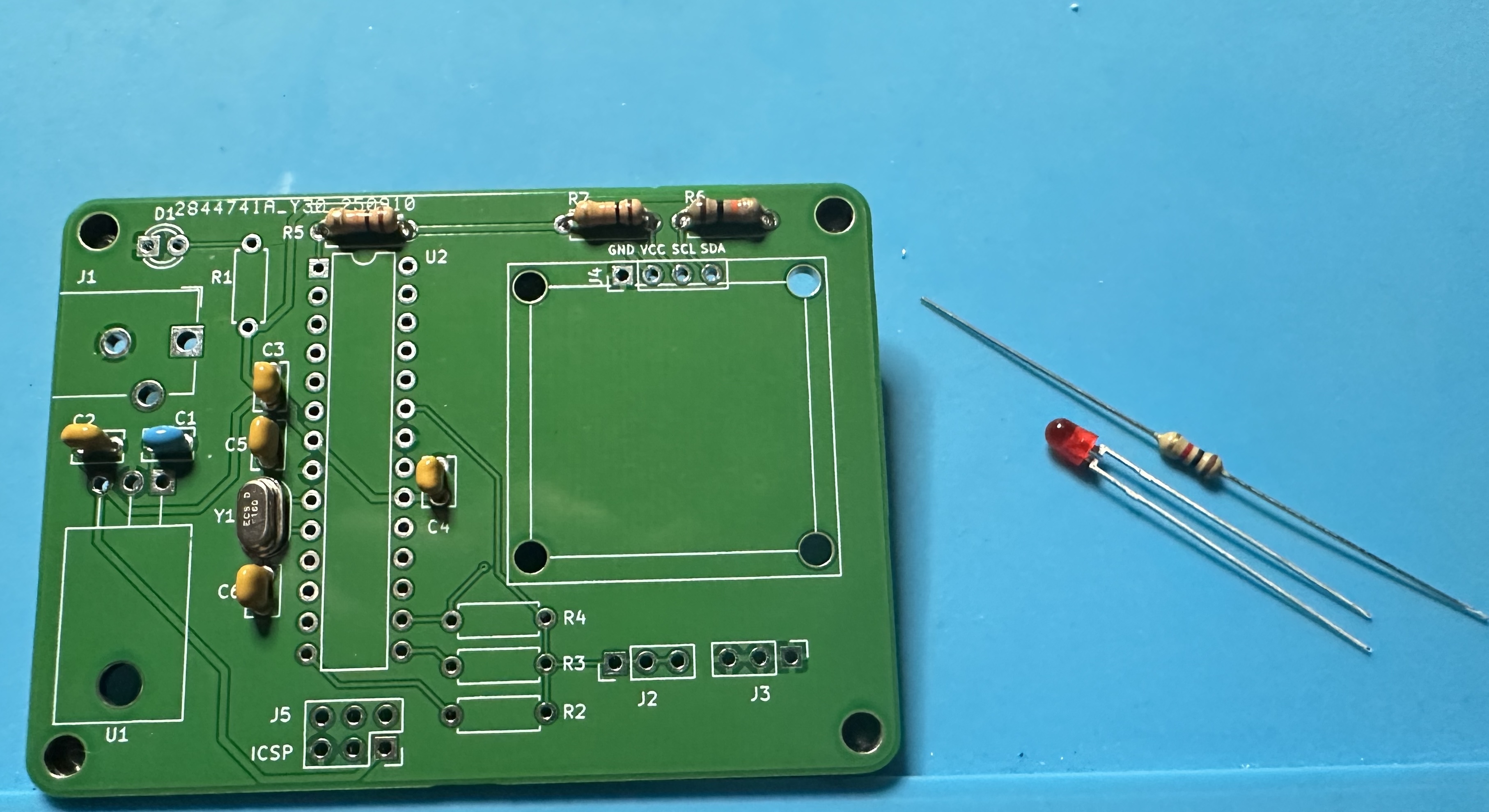
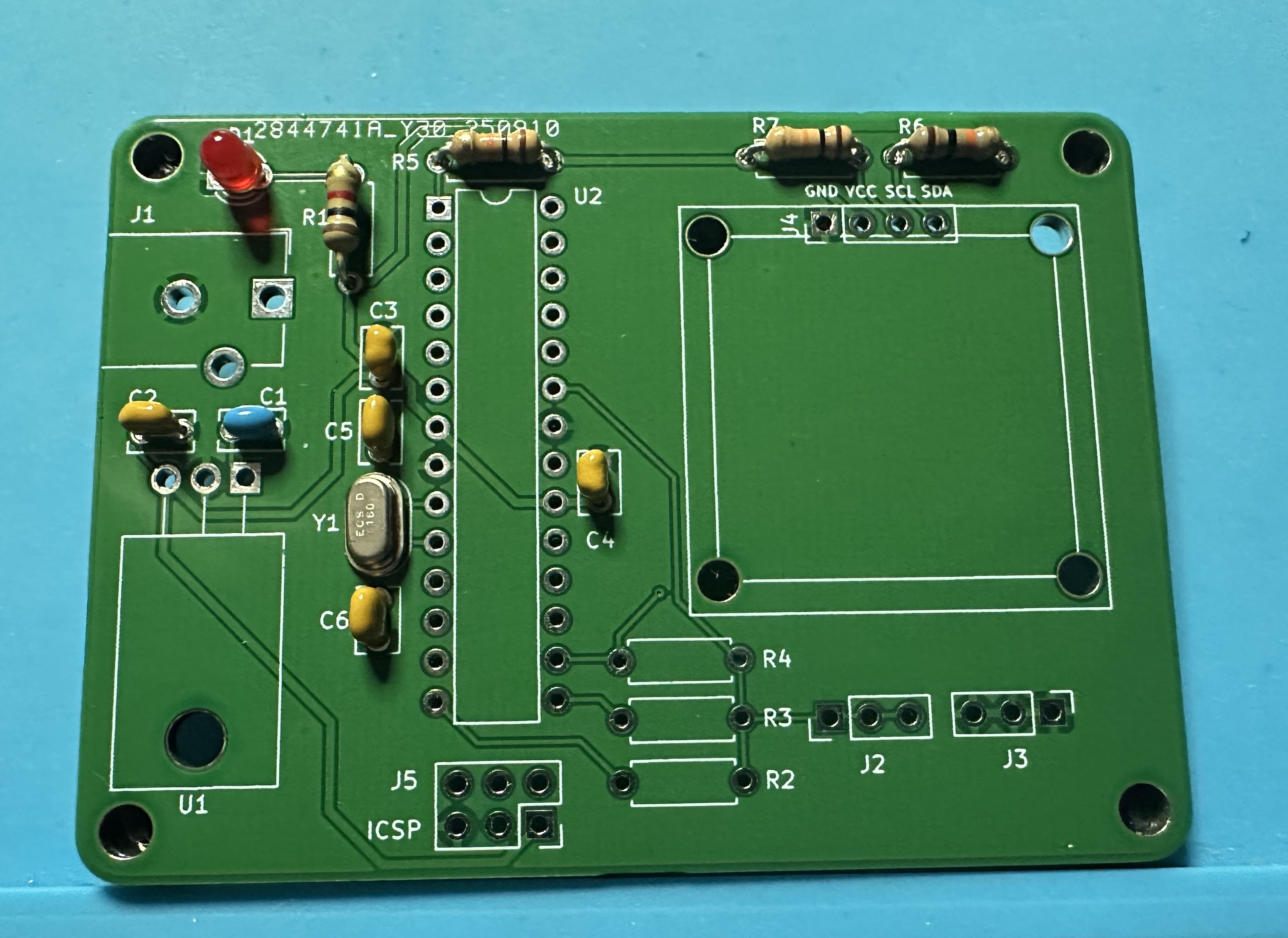
- Next up, add the "power on" LED D1 and its 1-kΩ limiting resistor.resistor (brown black red) in R1. The LED is directional — it must be soldered in with the correct orientation. The longer lead is positive and goes in the circular through hole. The shorter lead is negative, and it goes in the square through hole.
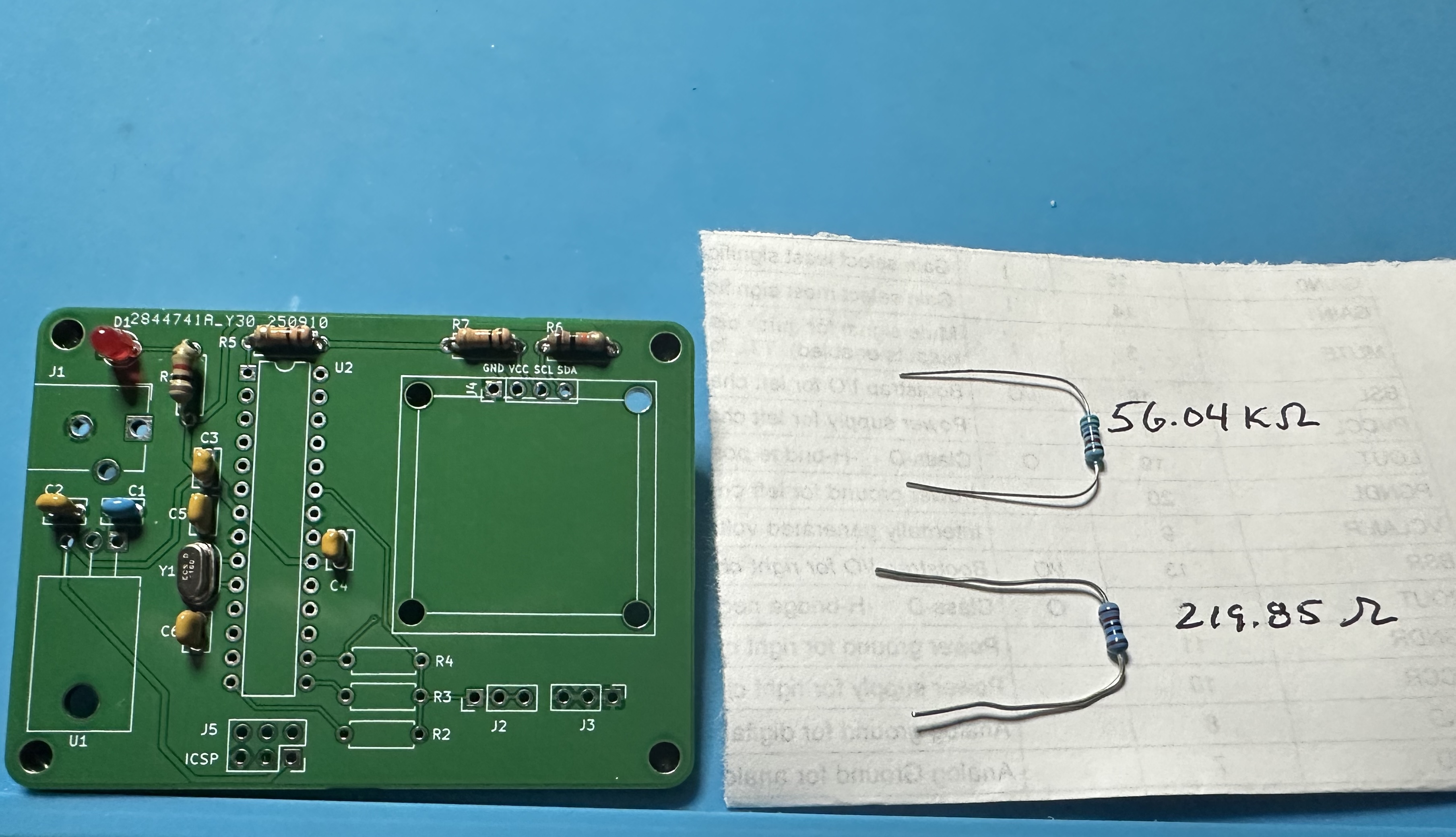
- Now add the two 1% resistors that are used for the voltage-divider measurement. They have a blue color and are hard to read. (220-Ω = red red black black and 56kΩ = green blue black red).It might be a good to measure them with the ohm-meter in the lab, so that you know which is which. Also, you can enter the measured values into the sketch and give a slight improvement to the measurements. The 220-Ω resistor is R2 and the 56kΩ resistor is R3. (Nothing goes into R4.) -
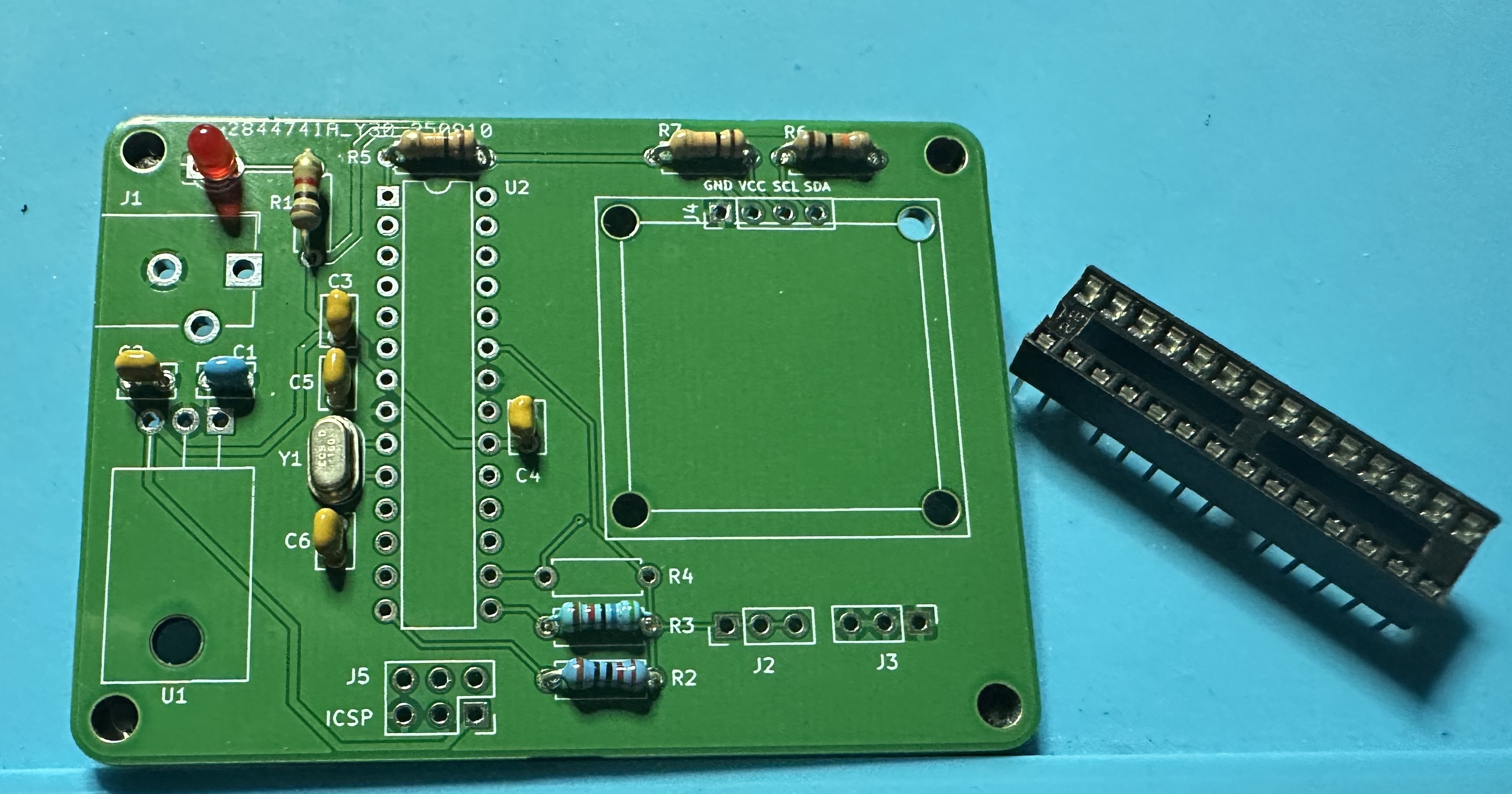
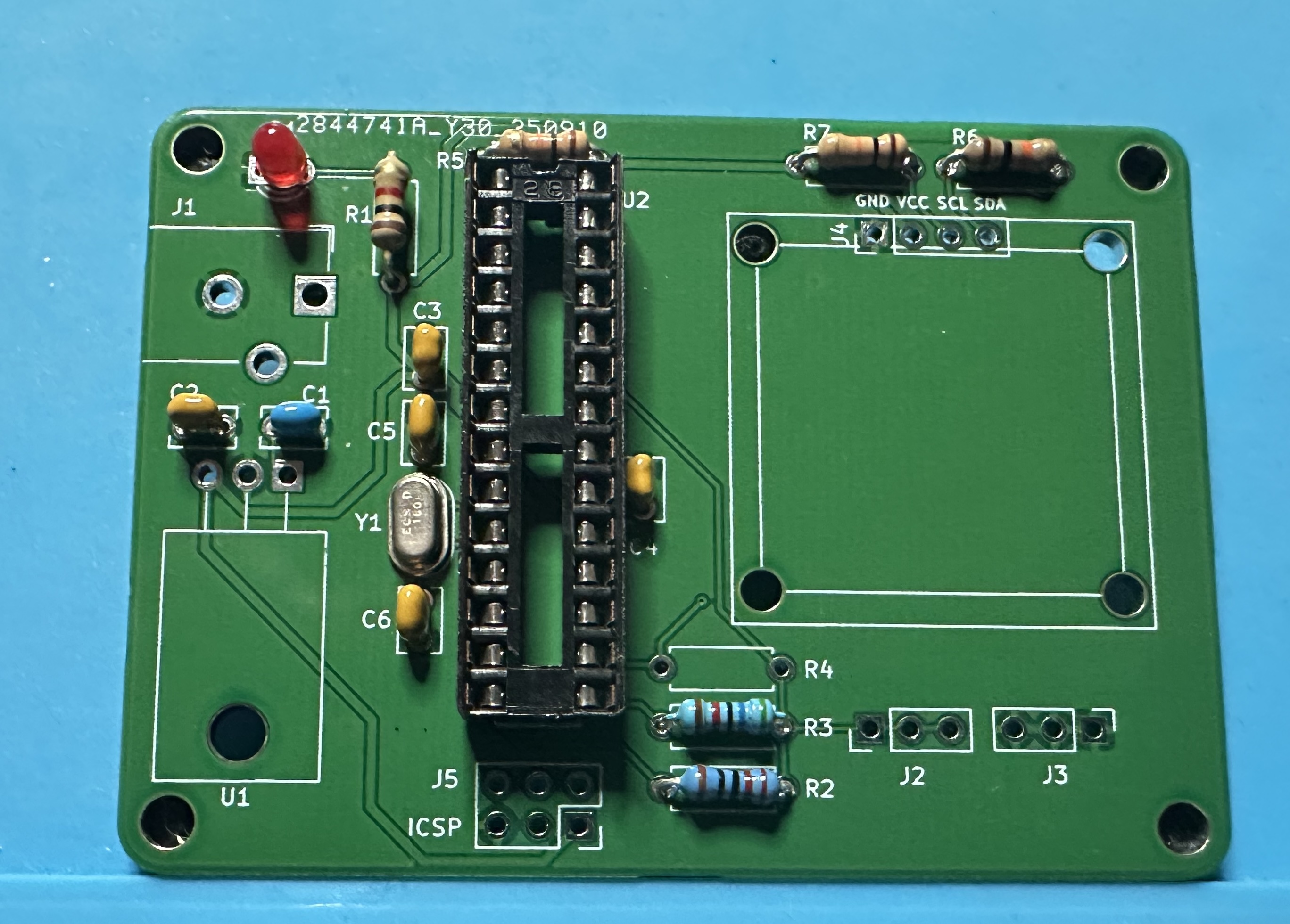
- Next up, add the chip socket — (U2) for the Atmega chip. This one is tedious — 28 pins. Solder one pin and check the alignment. Then take a deep breath and start soldering the other 27.
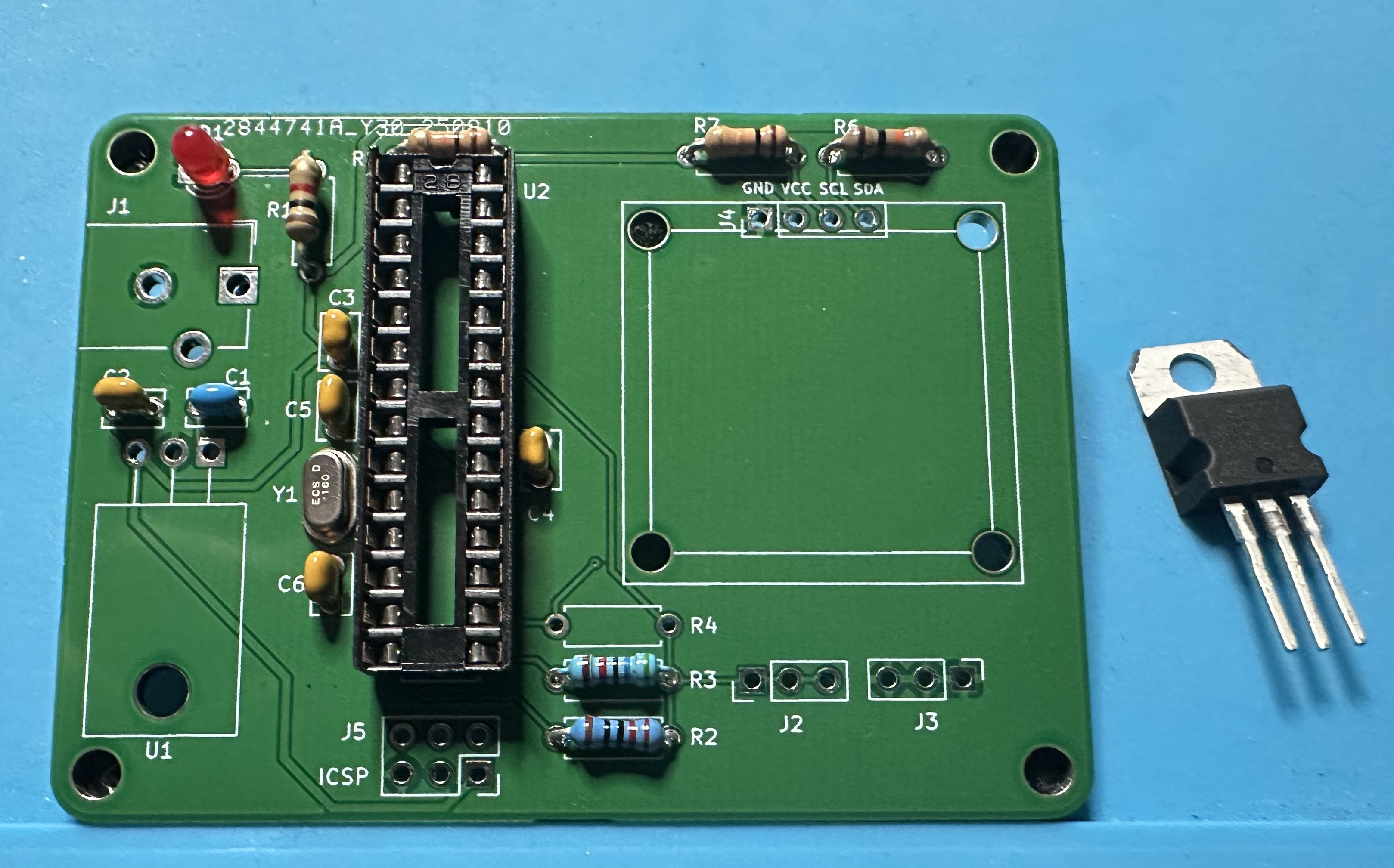
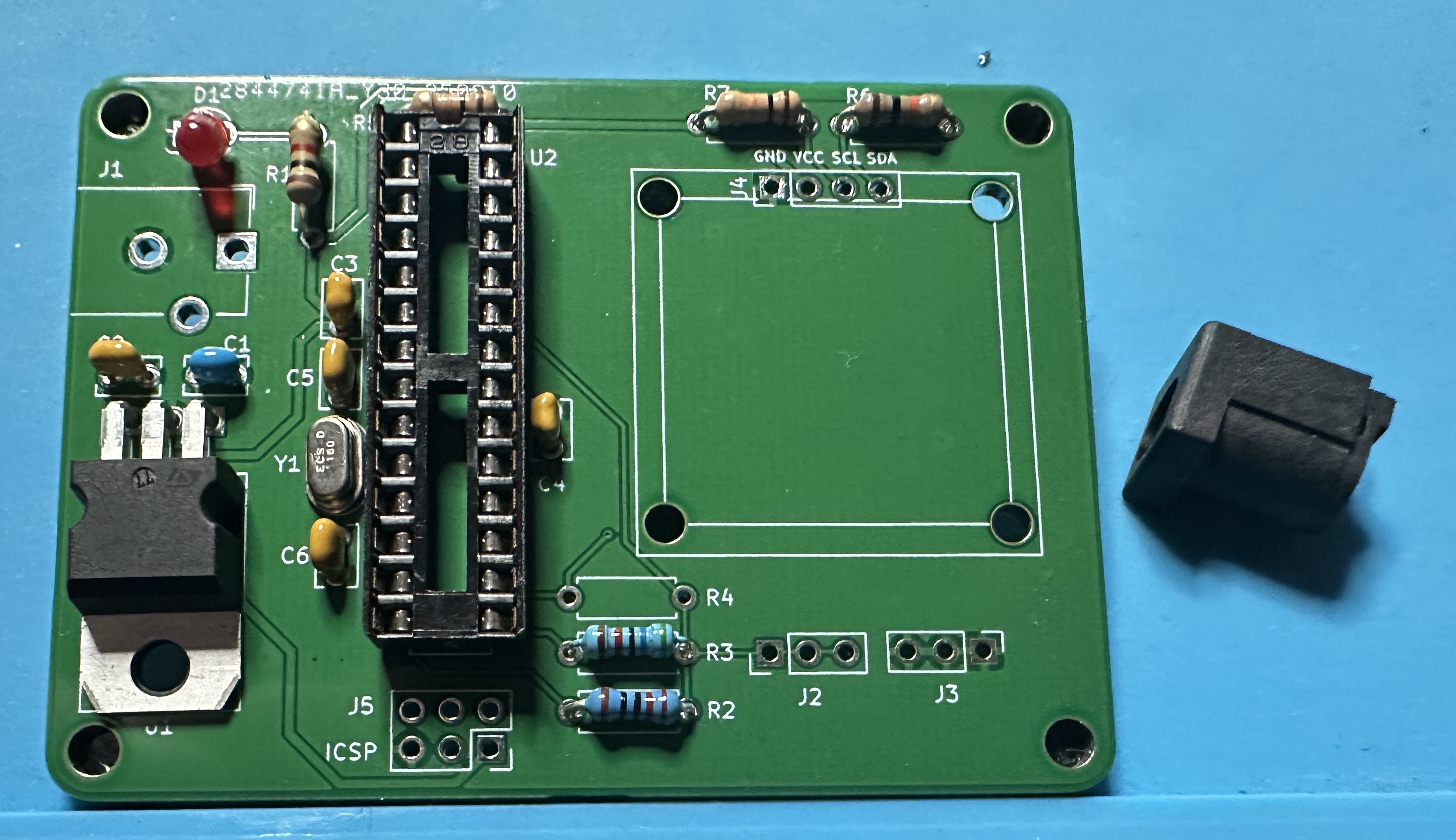
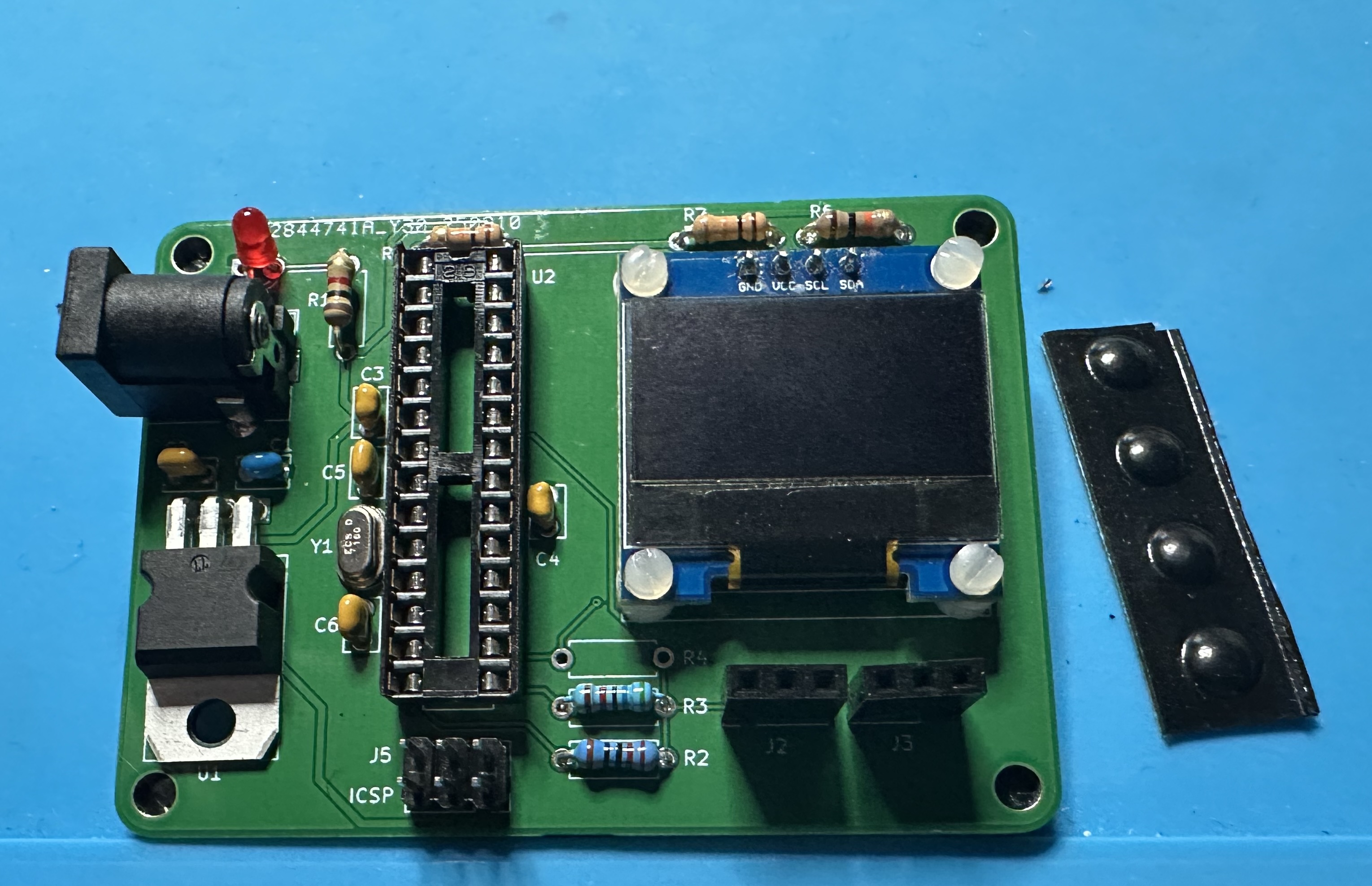
- The LM7805 voltage regulator. (U1). You leave standing straight up or bend the leads so that it lays down flat, as shown here. You will probably have to fiddle with the bending little bit to get a good fit.
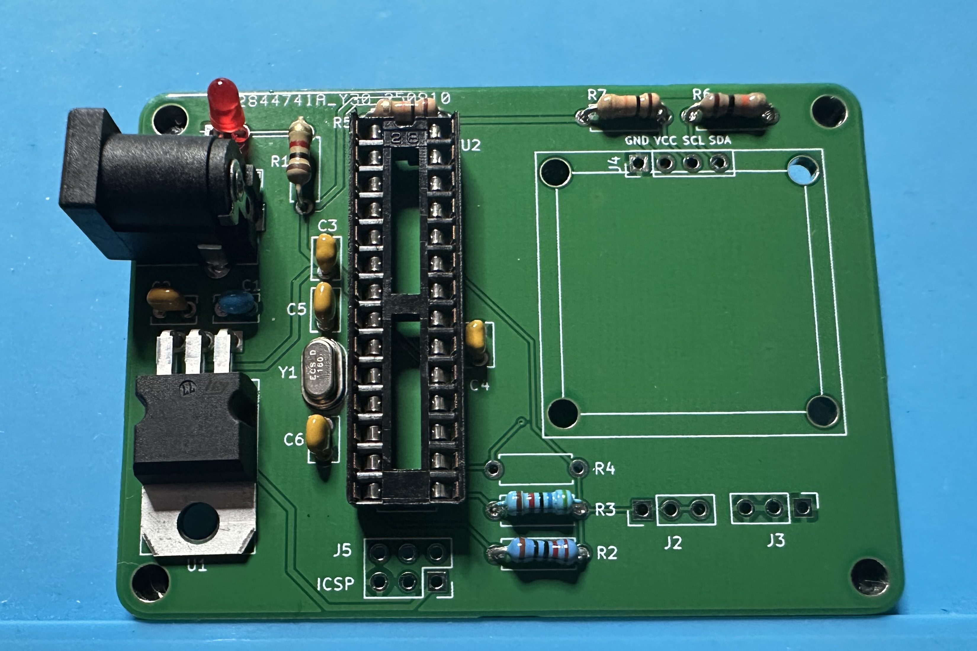
- Now, we can do the barrel jack for connecting the 9-V battery.
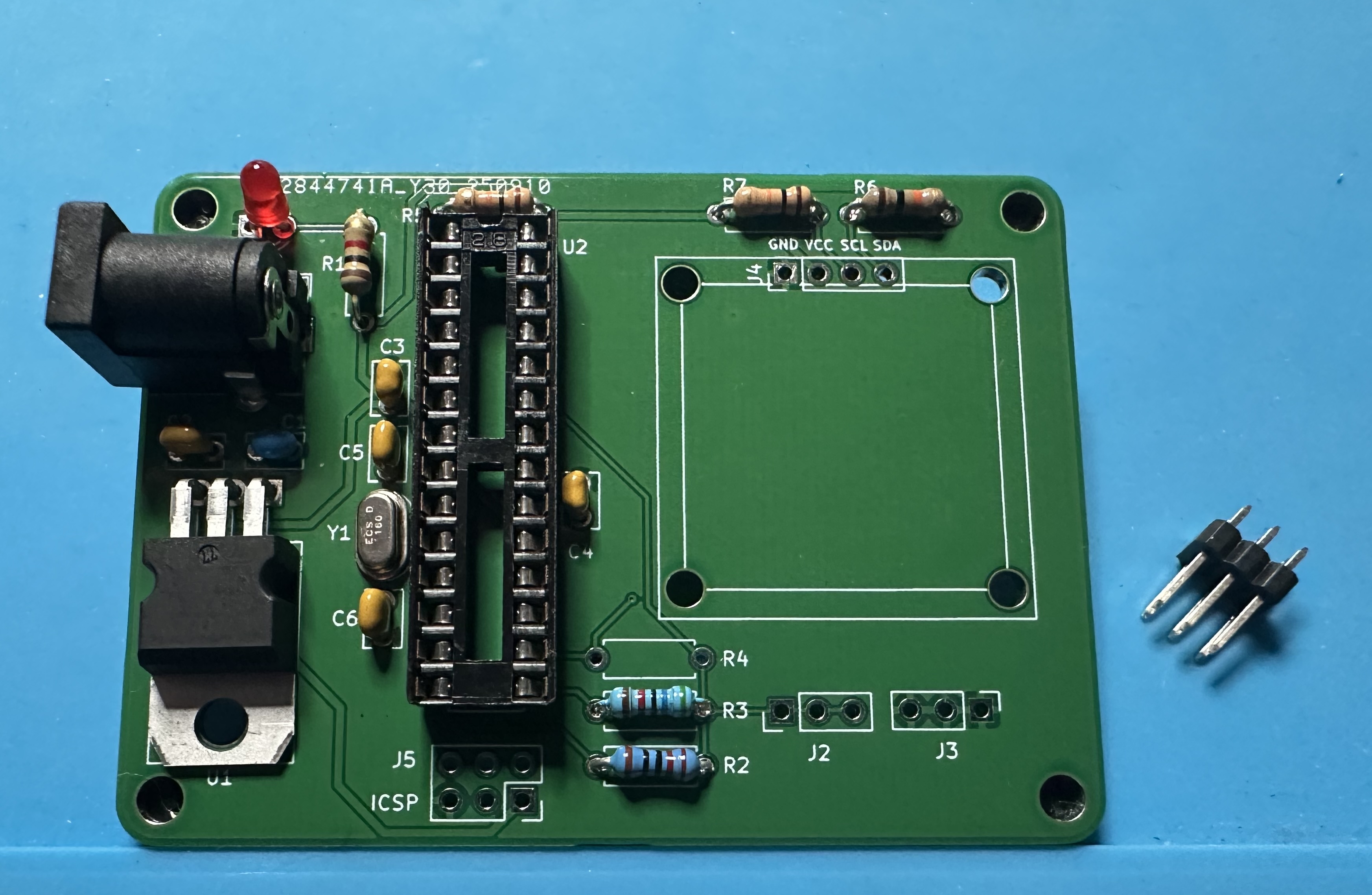
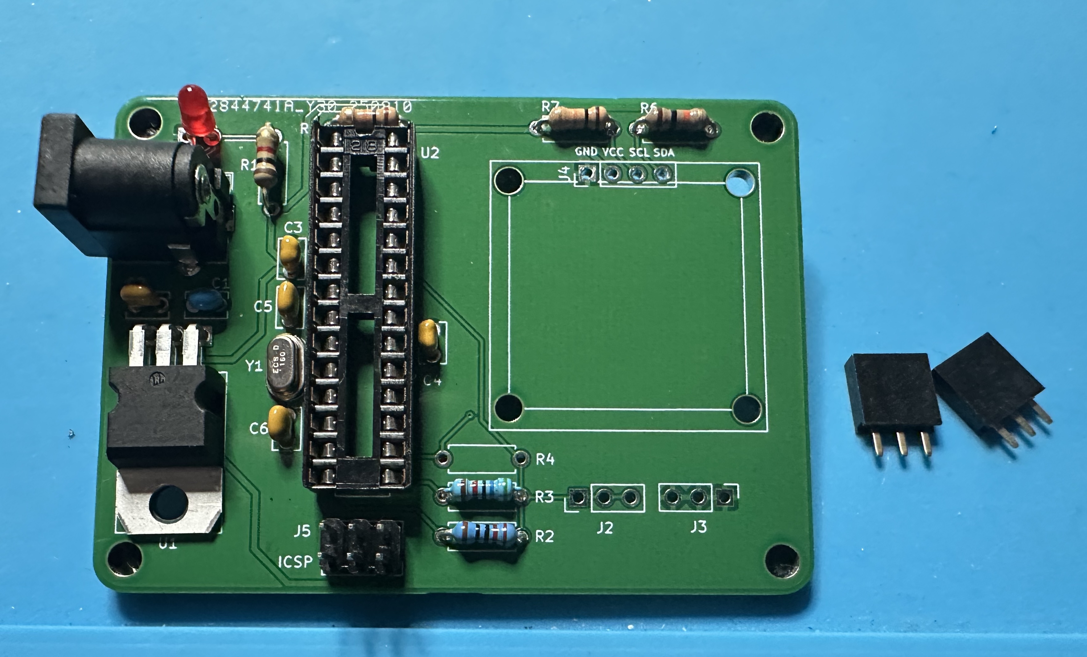
- The six-pin ICSP header in case you want to do external programming of the Atmega.
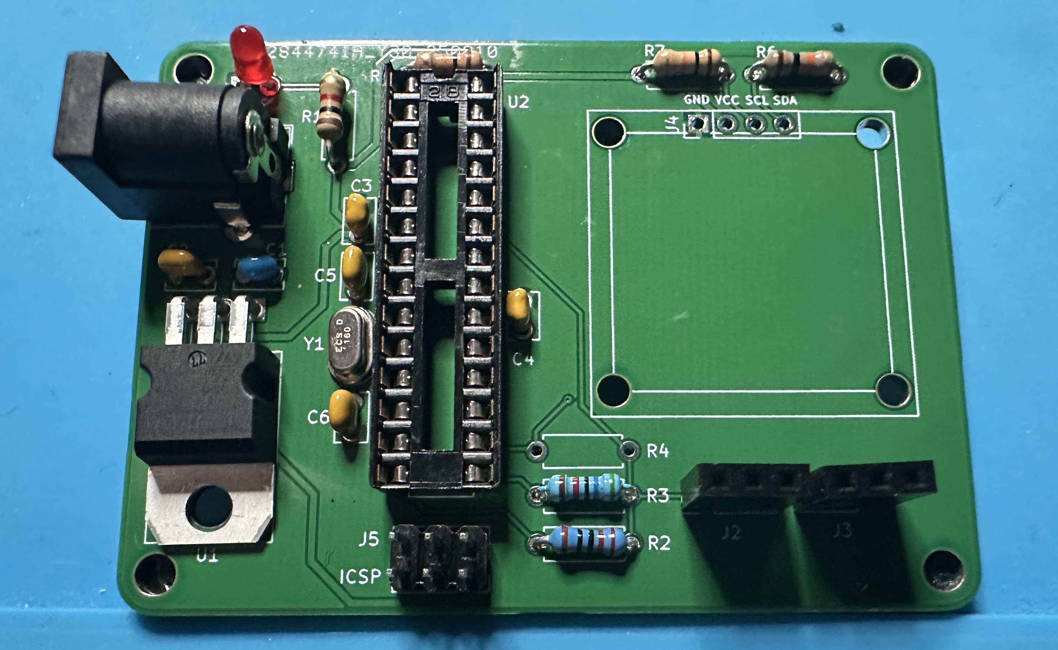
- Next up, the two 3-position female headers that will hold the resistor being tested.
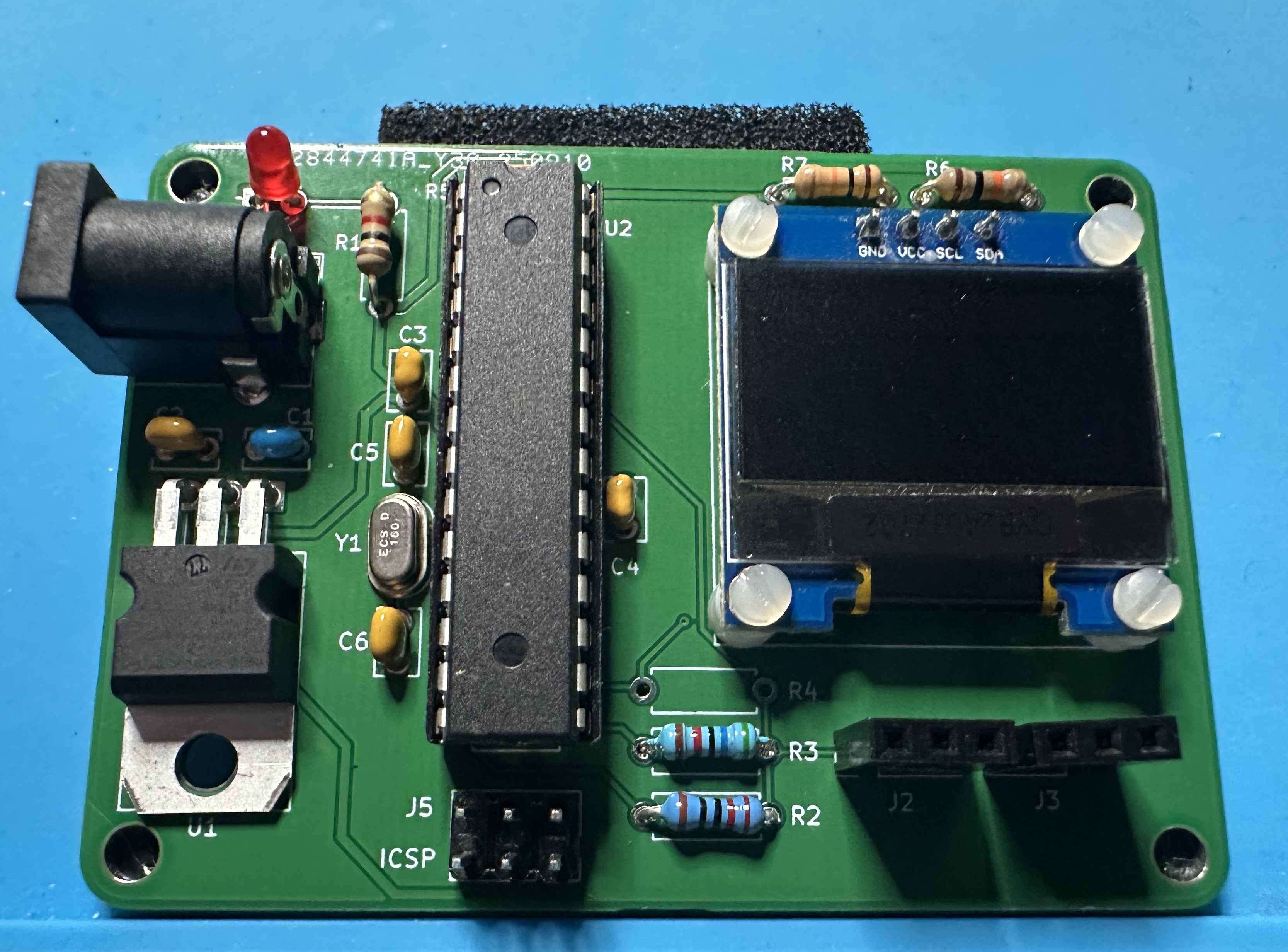
- Home stretch! Attach the OLED display and solder it in place. Suggested approach: Push all four of the nylon screws through the holes. It's a tight fit and you will need to apply a bit of force to get the screws through. (It will be OK!) The turn the display over and put the four spacers on the screws. Next turn the PCB over and insert it onto the display. Thread on the four nuts and use a screw driver to tighten everything up. Finally, solder in the four pins for the display.
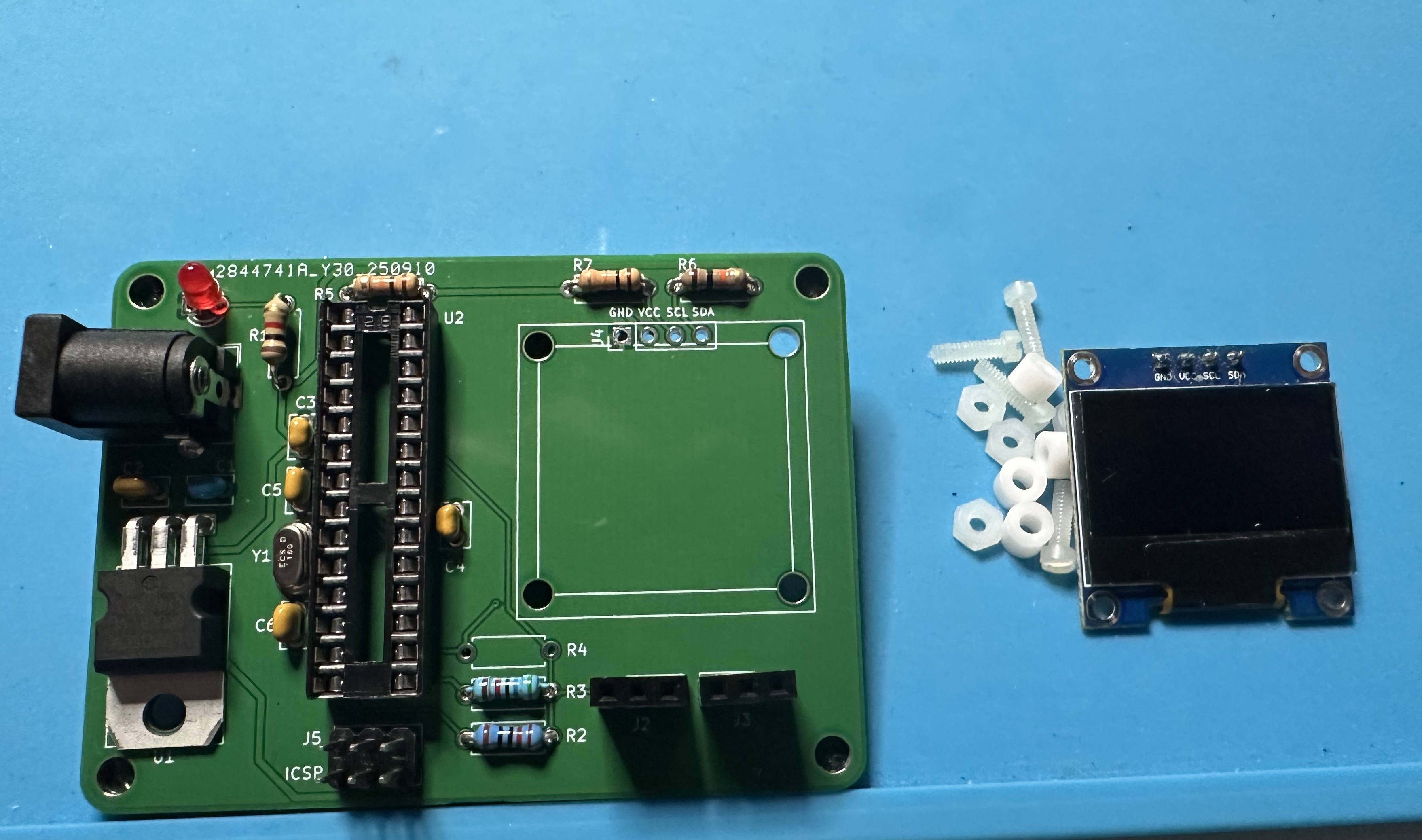
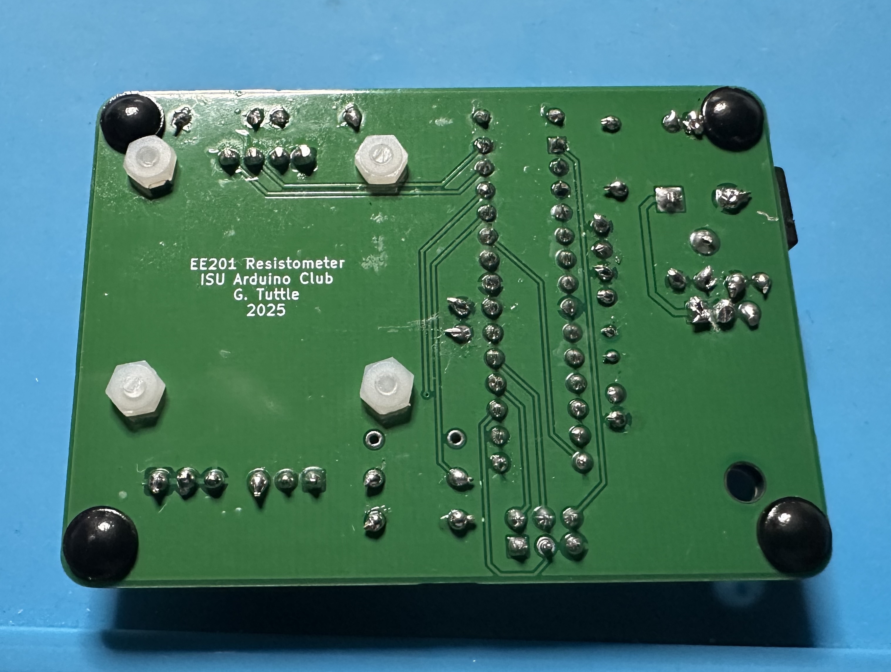
- Attach 4 bumper feet to the bottom corners, so that the board sits level when you are using it. You will probably need to use an exacto knife to trim off the excess length of the nylon screws. (But don't cut yourself!)
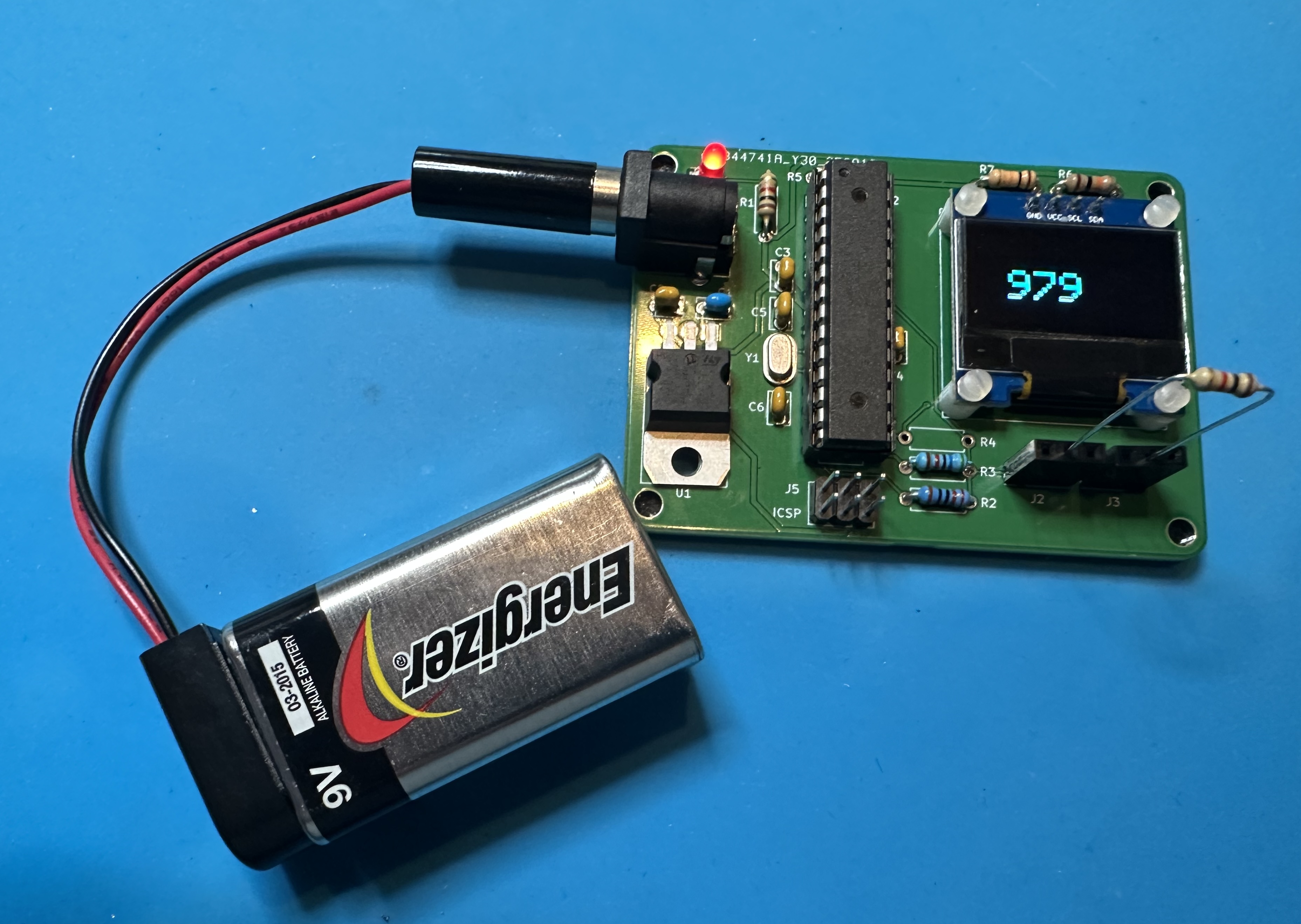
- To finish up, insert the Atmega328 chip into the socket. You can program before installing or after, using the ICSP header. You will probably have to fiddle with the leads, bending them in a bit so that all leads fit into the socket. Don't force it! Once the chip is programmed, attach a battery and start measuring resistors!