ISU Audio and Arduino Club
Desktop speaker build instructions
- Below are (most of) the step-by-step instructions for building the Speaker project.
- This build will take the longest time of any of our projects, by far. We have allotted two weeks of meeting time to building, and you will likely need to spend some extra time outside of the meetings, too.
- There are three main parts to the builds: glueing together the wood for the enclosures, soldering the crossovers, and final assembly. Instructions for the glueing and soldering parts are given below. Instructions for final assembly will be available in a couple of days.
- In addition to the usual tools for soldering, some extra items will be needed: wood glue, clamps or weights for pressing the box parts together while the glue dries, sandpaper (or a power sander), wood filler and paint for finishing the boxes. Glue, a few clamps, and some items to use as weights will be available at the meetings.
- All of the photos are links; click on them to open new browser windows with a higher resolution image.
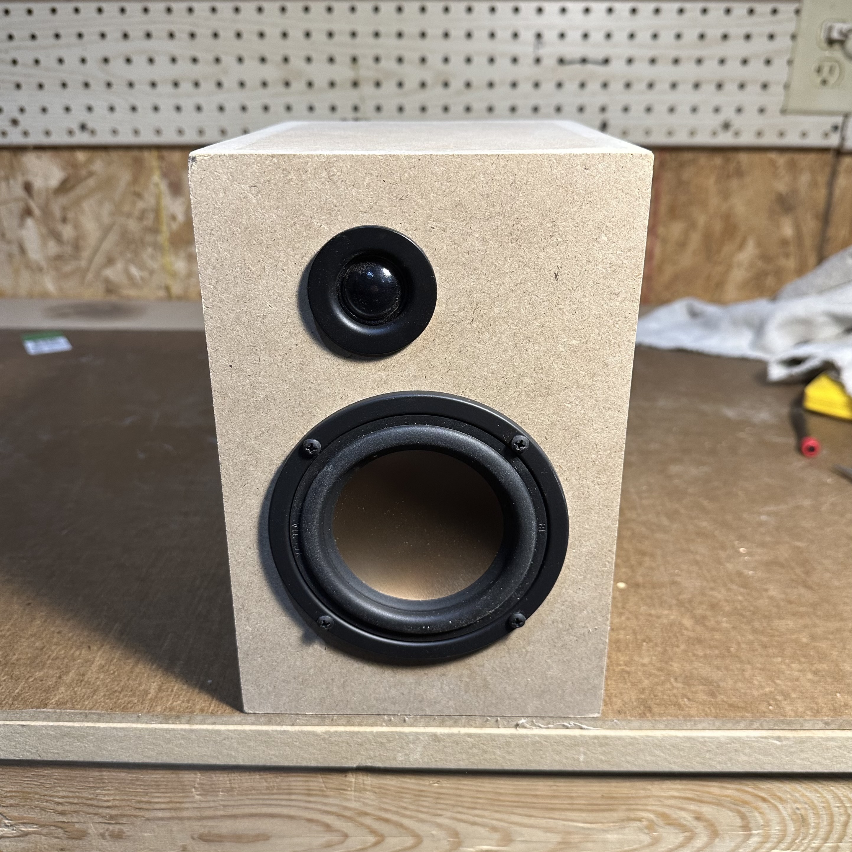
Part 1 — enclosure
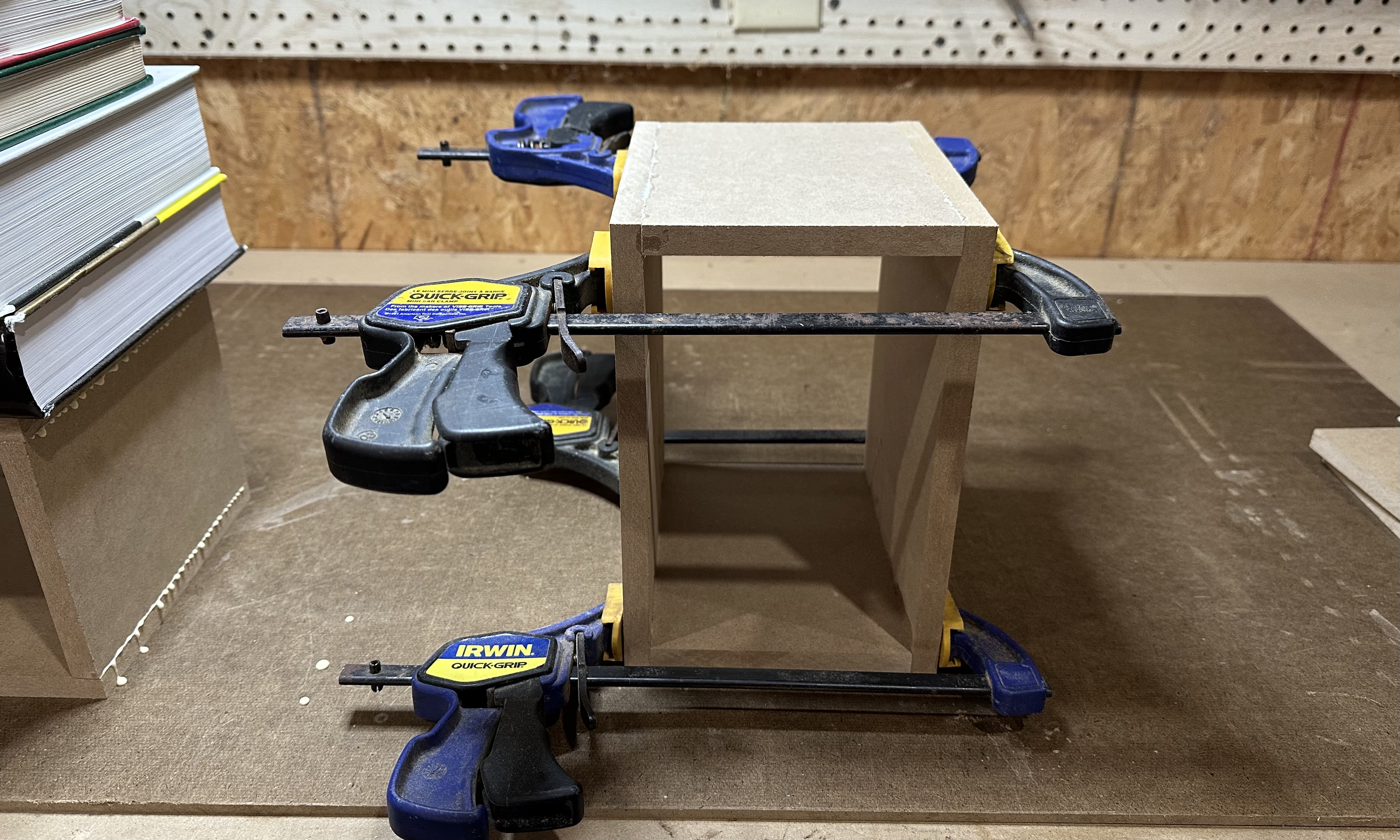
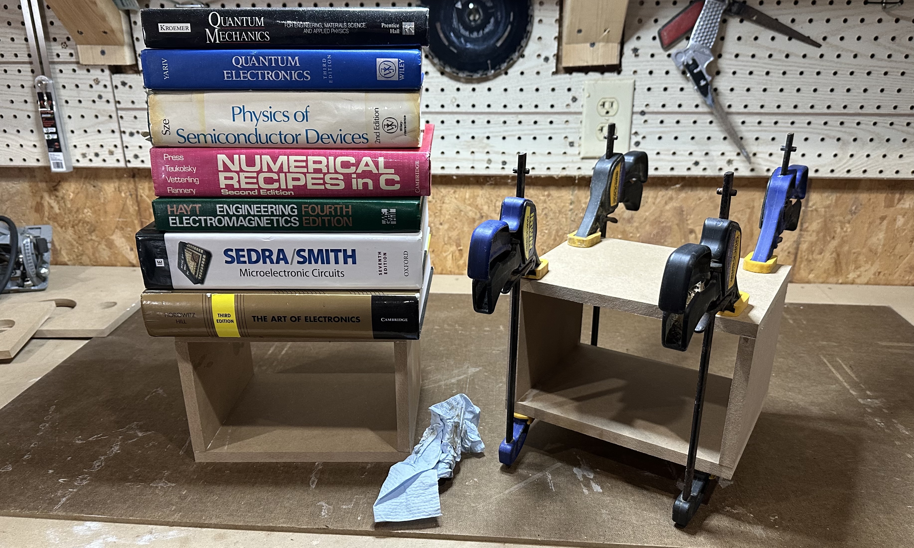
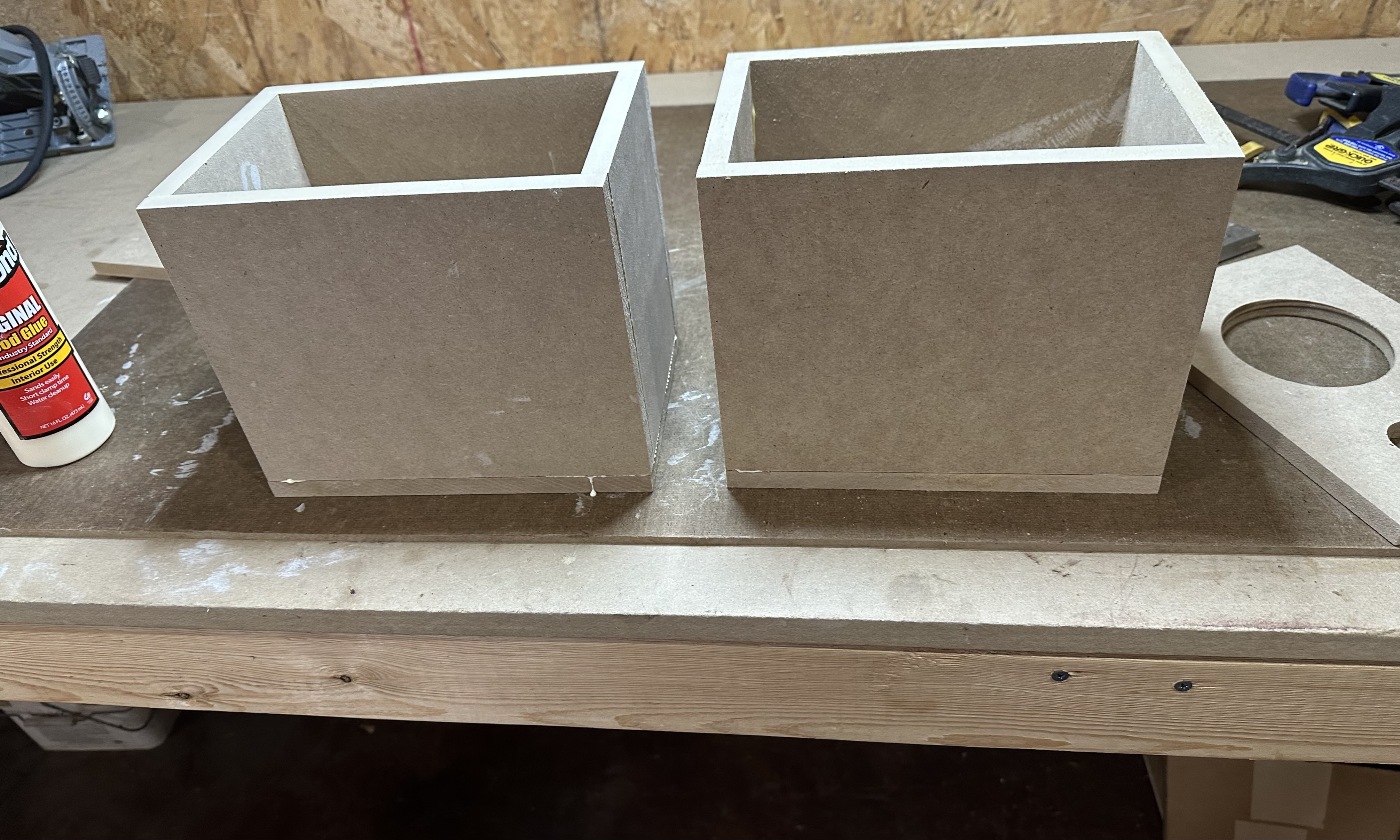
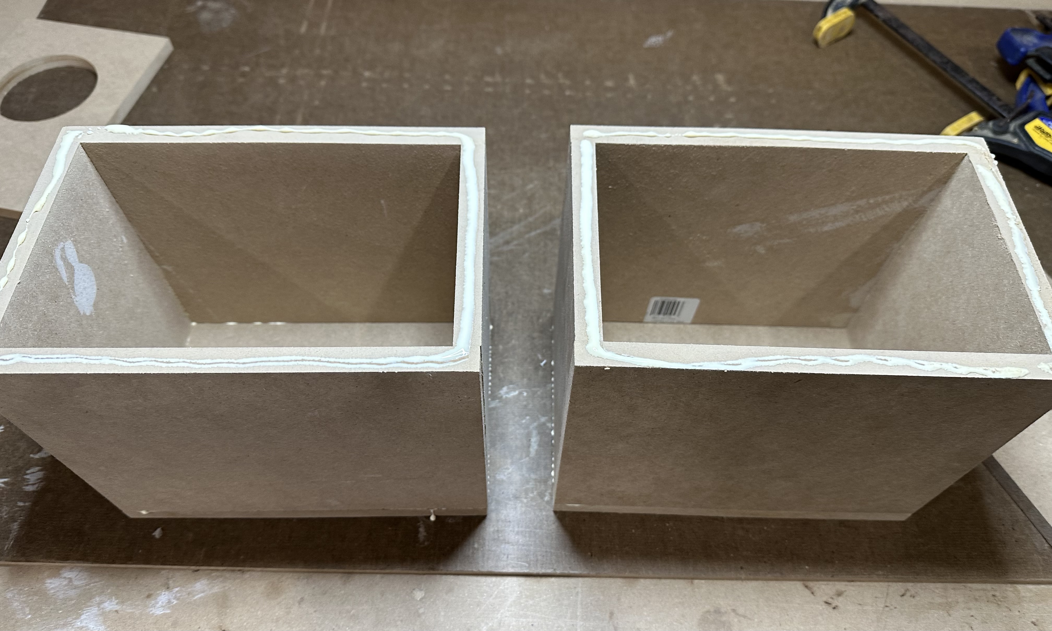
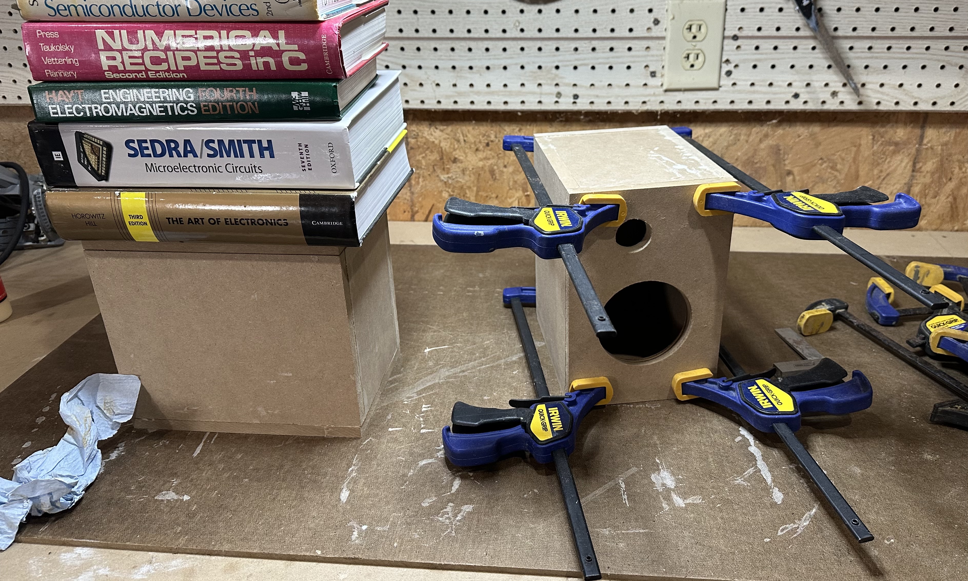
The speaker project requires two identical speaker boxes. Probably the best approach for the inexperienced is to do them one at a time rather than in parallel. The text of the instructions below is written with the assumption that the two boxes are being done sequentially. However, the photos show the two boxes being at the same time in order to show the use of both weights (in the form of a stack of text books) and clamps to hold the boxes together as the glue dries.
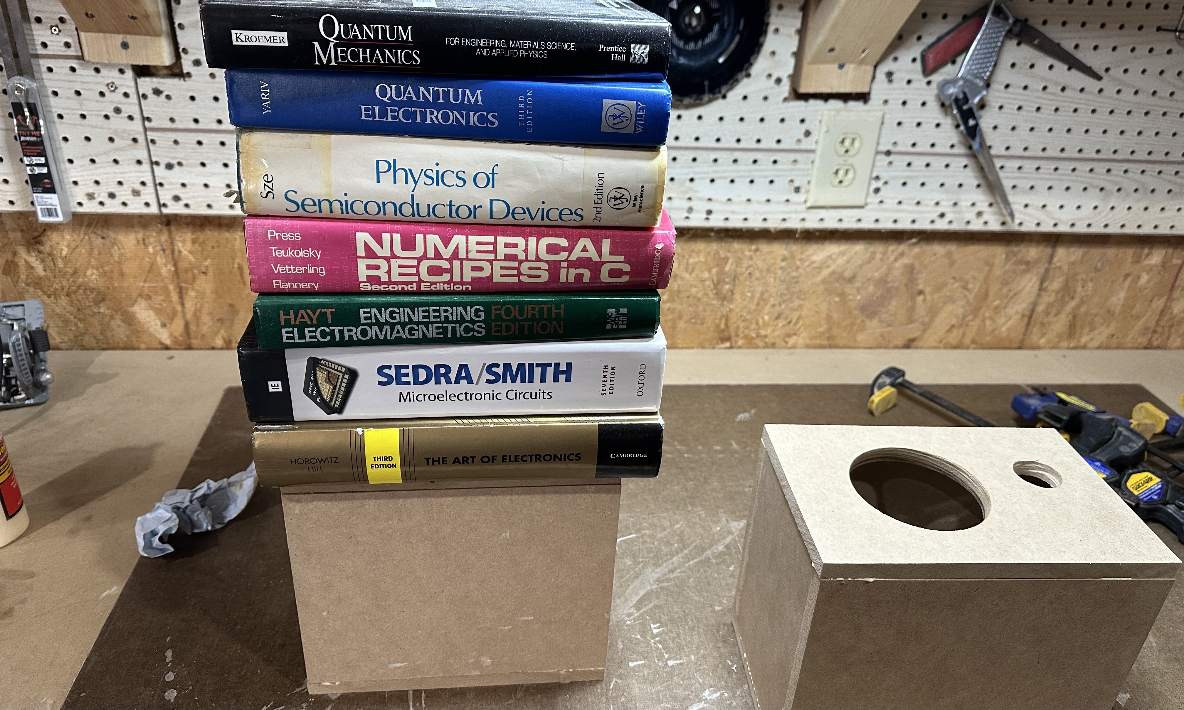
Many things can be used as a weight while the glue dries: a few books as shown here, a gallon jug of water, a couple of bricks, an oscilloscope, a sleeping roommate. Eight to ten pounds (4 to 5 kilos) of weight should be adequate.
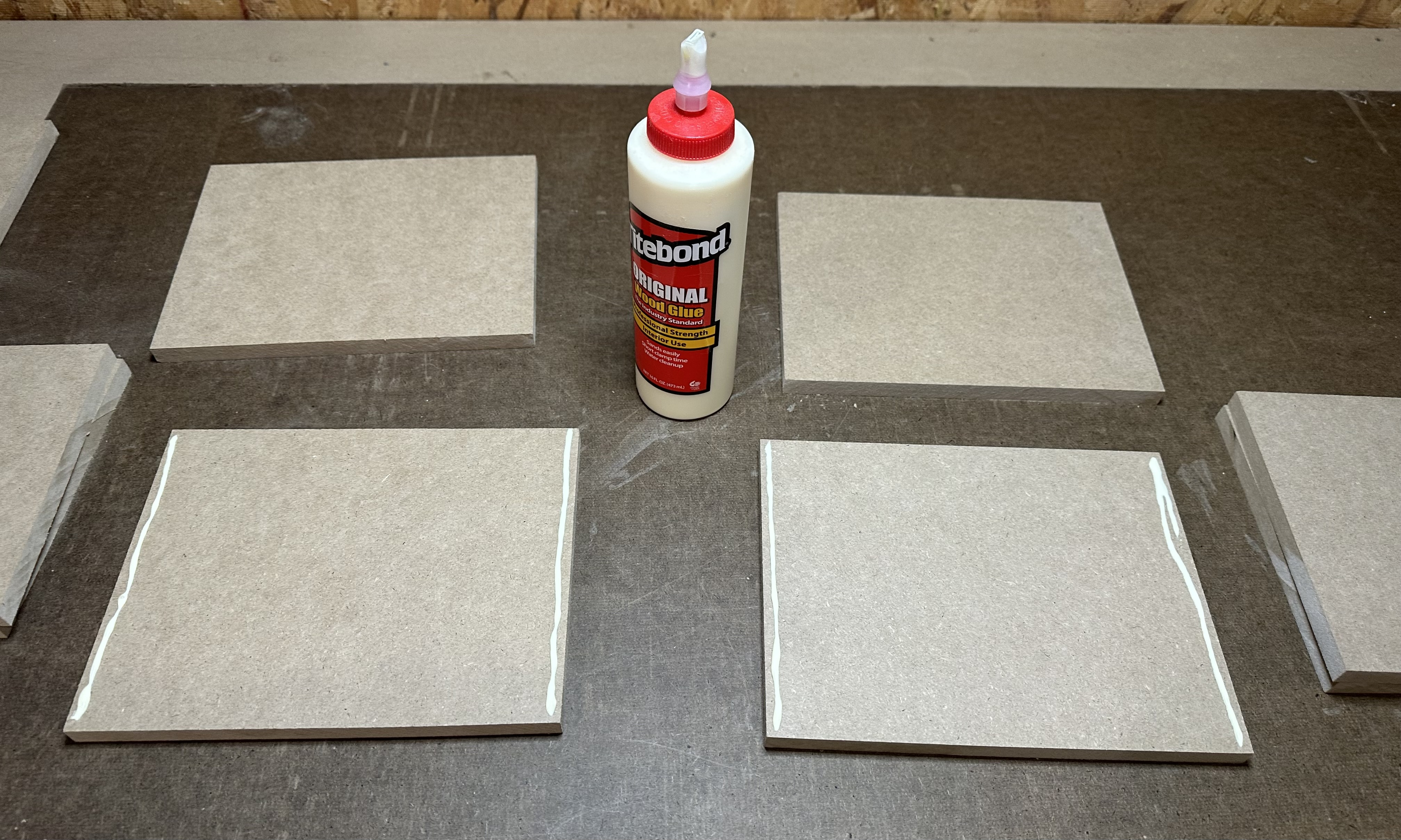
- Assemble the parts. There should be six medium-density fiber board (MDF) panels for each speaker:
- Two 9" x 7" panels for the sides.
- Two 9" x 6' panels for the front and back.
- Two 7" x 5" panels for the top and bottom.
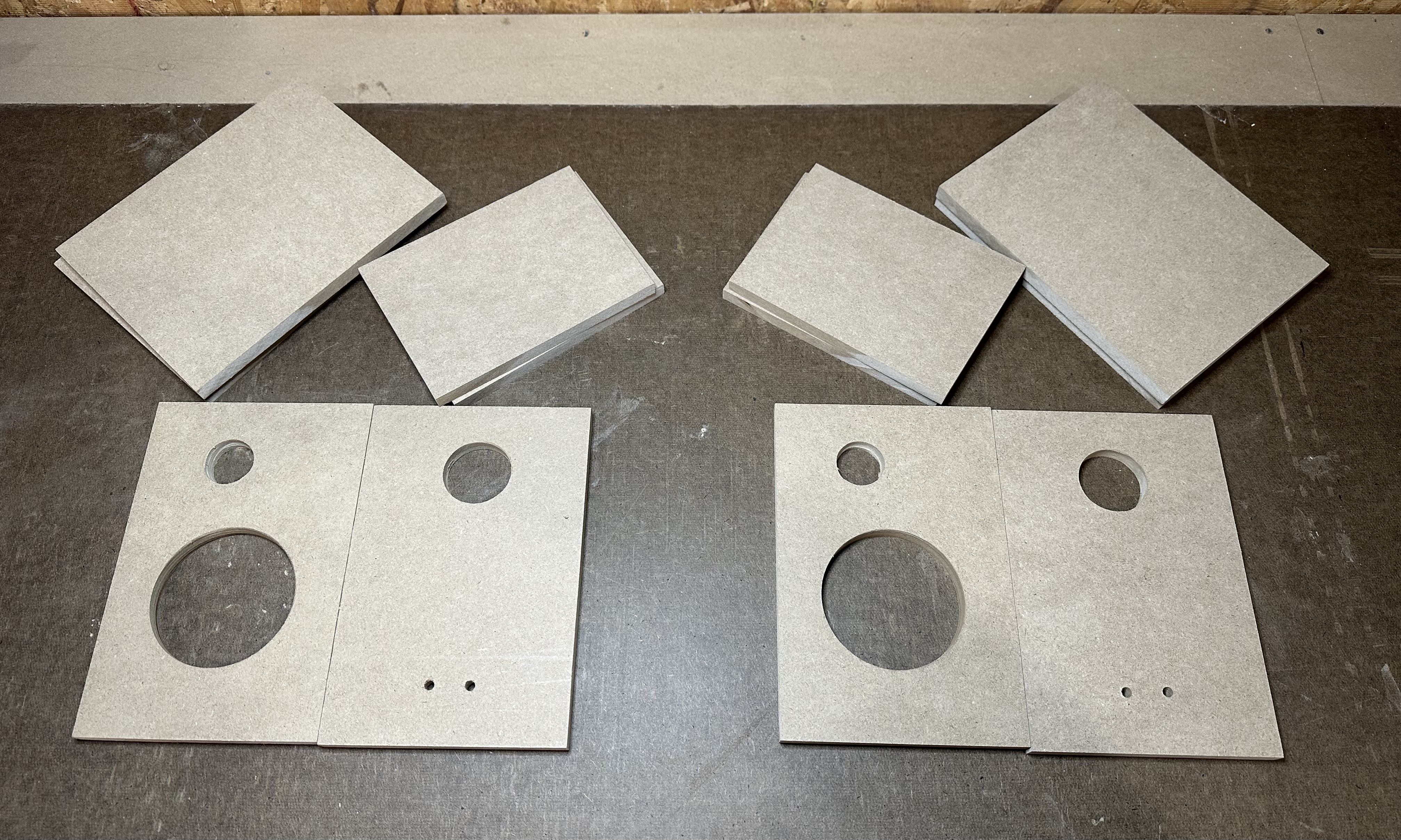
- Dry fit the panels to ensure that everything fits and that you understand the basic arrangement of the parts.
- Lay one of the side panels flat. Apply thin beads of glue along the shorter (7") sides.
- Stand the top and bottom panels vertically on the side panel, with the edges set in the glue on the side panel.
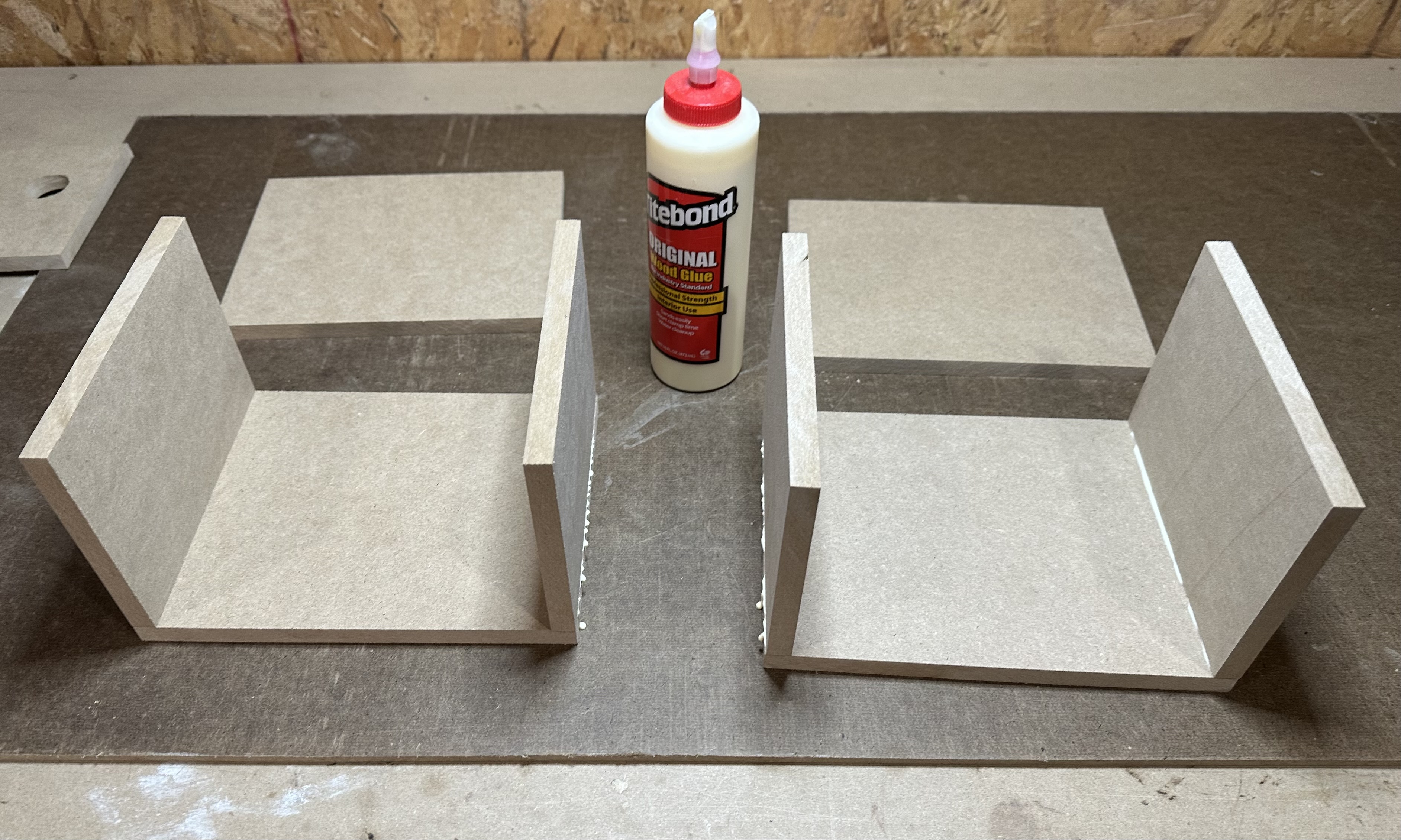
- Apply thin beads of the glue to the upper edges of two panels that are sitting vertically.
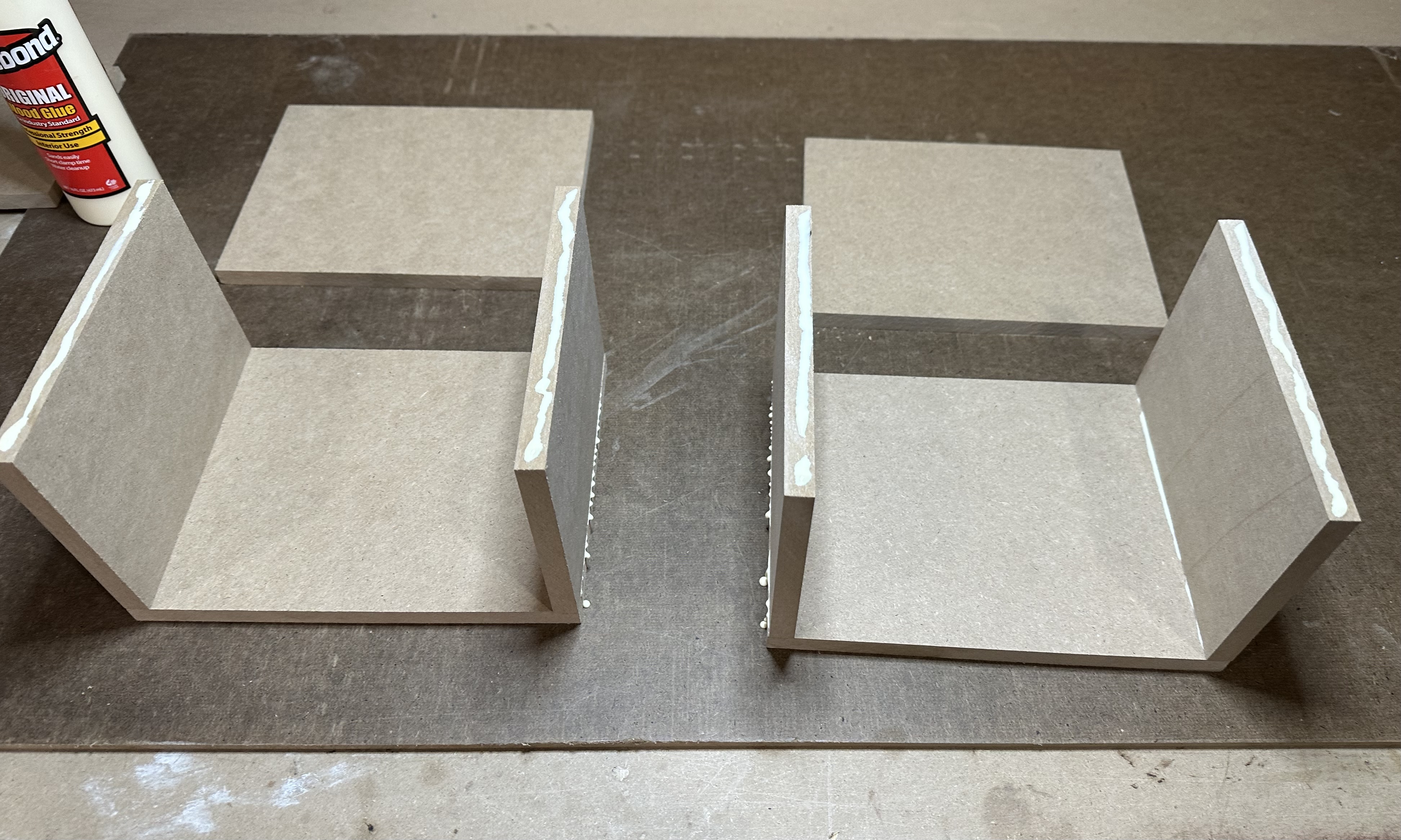
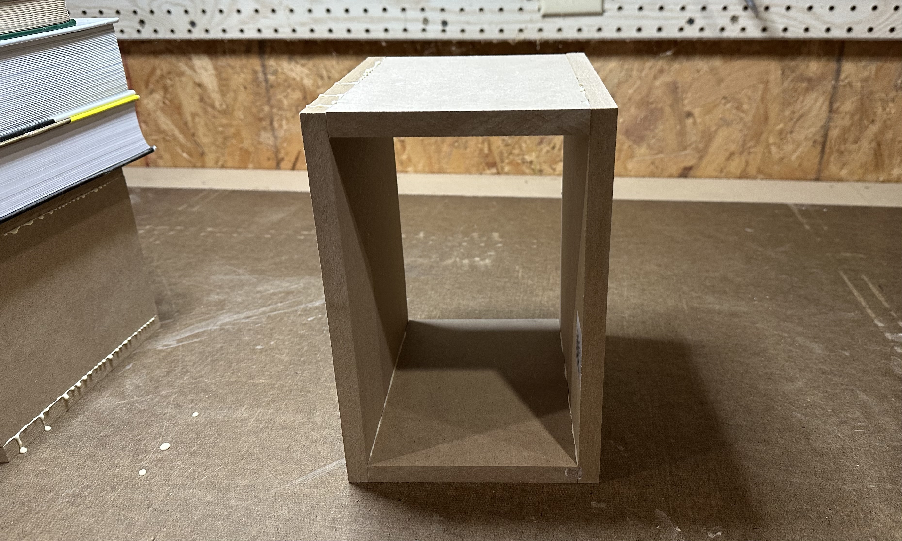
- Set the other side panel on top of the two vertical panels to form an open-ended box. While the glue is wet, adjust the position of the panels so that the edges are pretty well aligned all the way around. Note that the structure is pretty unstable at this point. Don't knock it over — the result would a gluey mess to clean up.
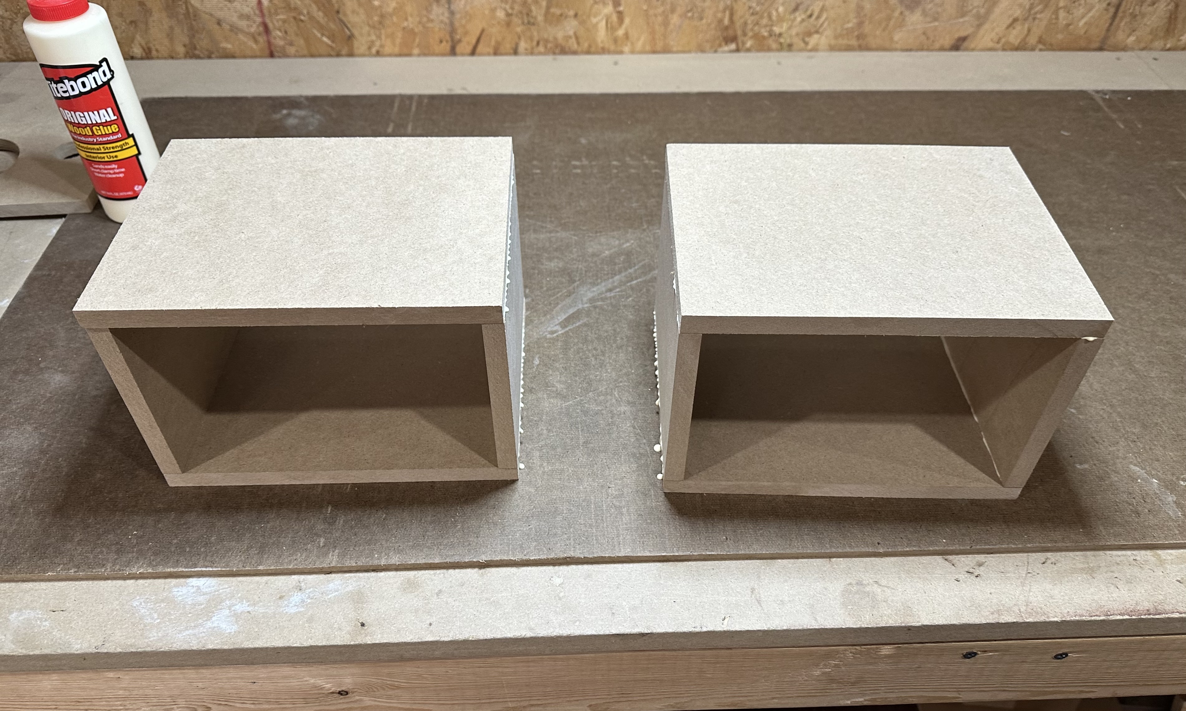
- If you are using a weight to hold everything in place while the glue dries, put the weight on now.

- If you are using clamps to hold everything in place, carefully tip the box so that the open ends are "up" and "down". Then apply two clamps to the sides. Snug the clamps down, but don't tighten them all the way. Once the clamps are tightened, the whole arrangment can be moved in whatever orientation is convenient.
- Whether using weights or clamps, make final adjustments to align the edges. Check and double-check alignment all around. The better the alignment at this stage, the less sanding and wood filling that will be needed later. Be prepared to wipe up excess glue that is squeezed out of the joints as pressure is applied.
- Before the glue begins to harden, check the alignment one more time and adjust if needed.
- Repeat all steps above to assemble and glue the four panels of the other box.
- Allow the glue to dry, at least 30 minutes.
- Once glue is dried, remove the weight or clamps. Inspect the edges where the front and back panels will be attached. if needed, sand them to remove any rough spots or steps.
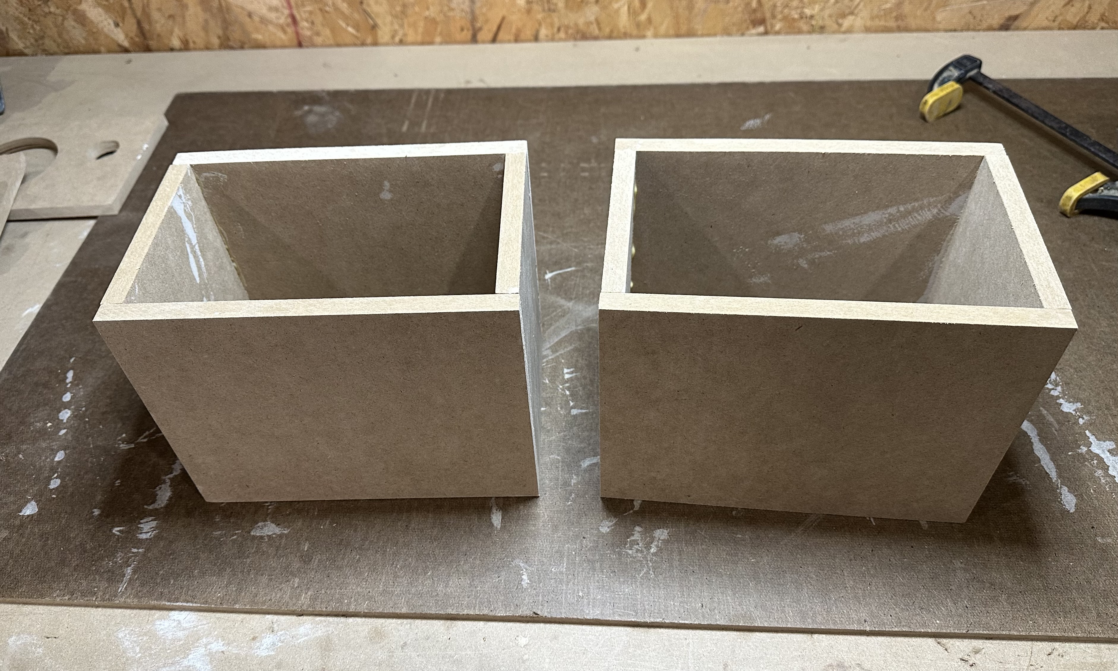
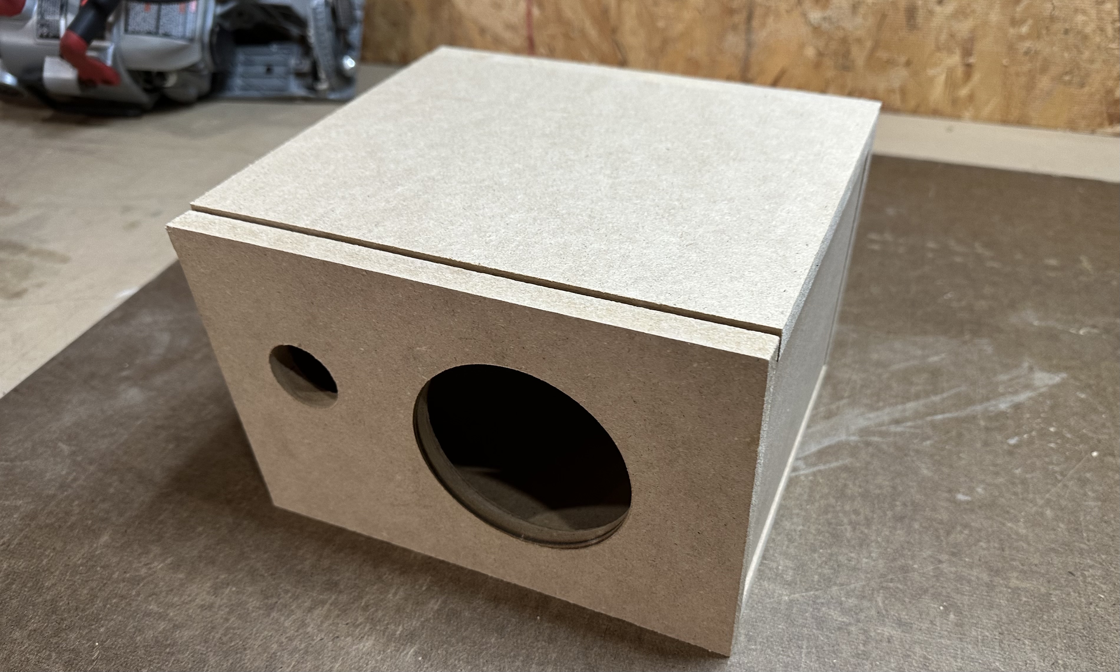
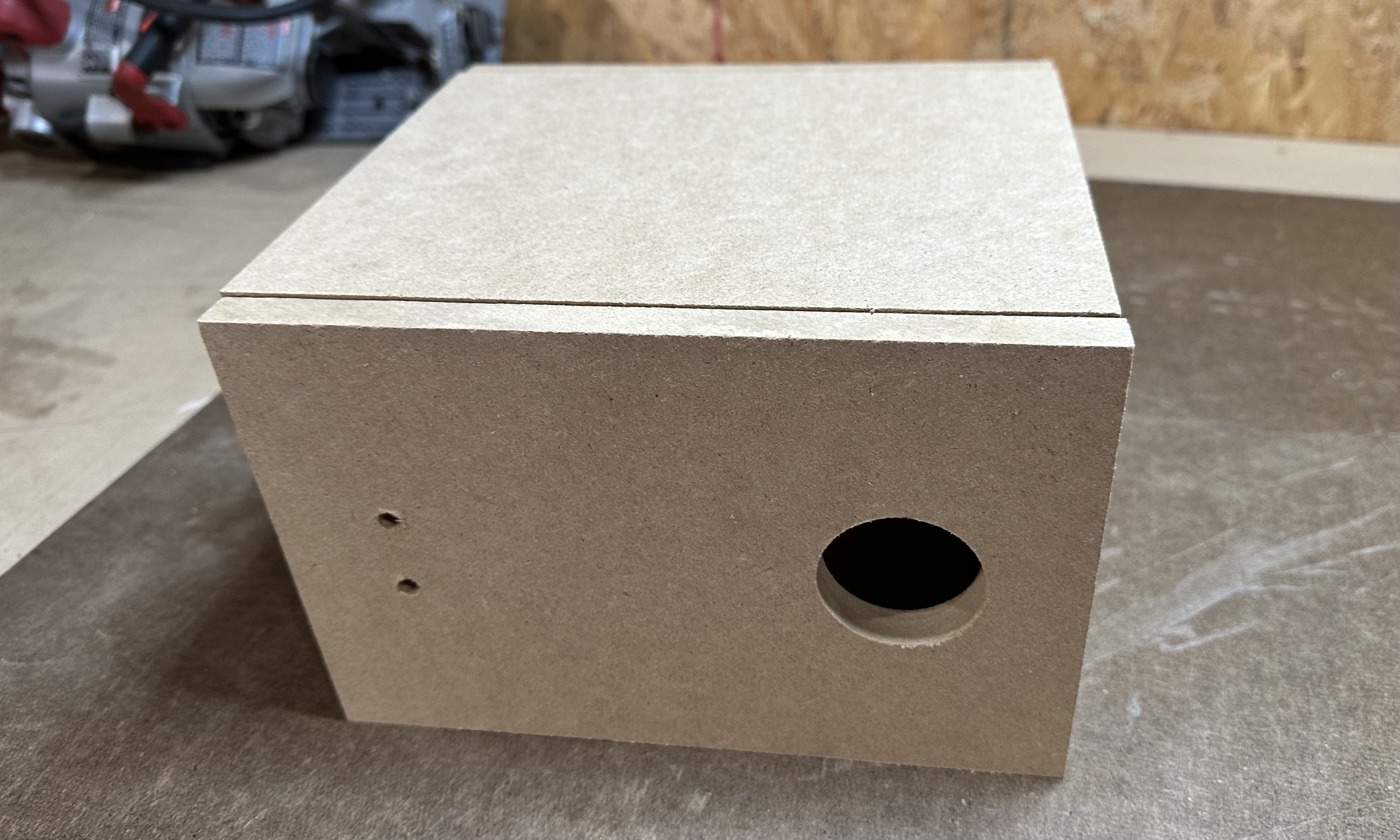
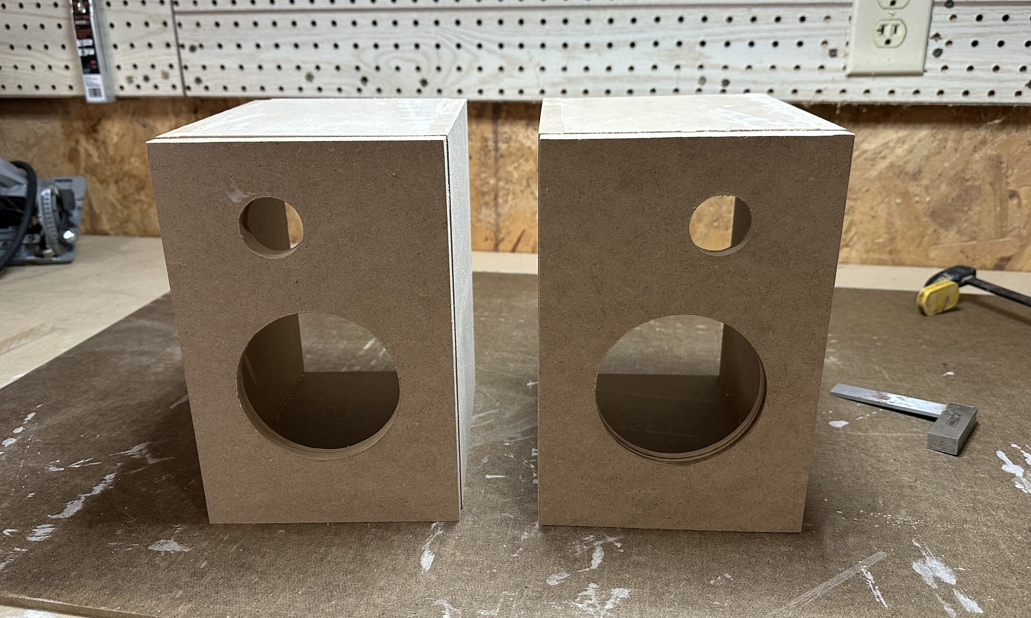
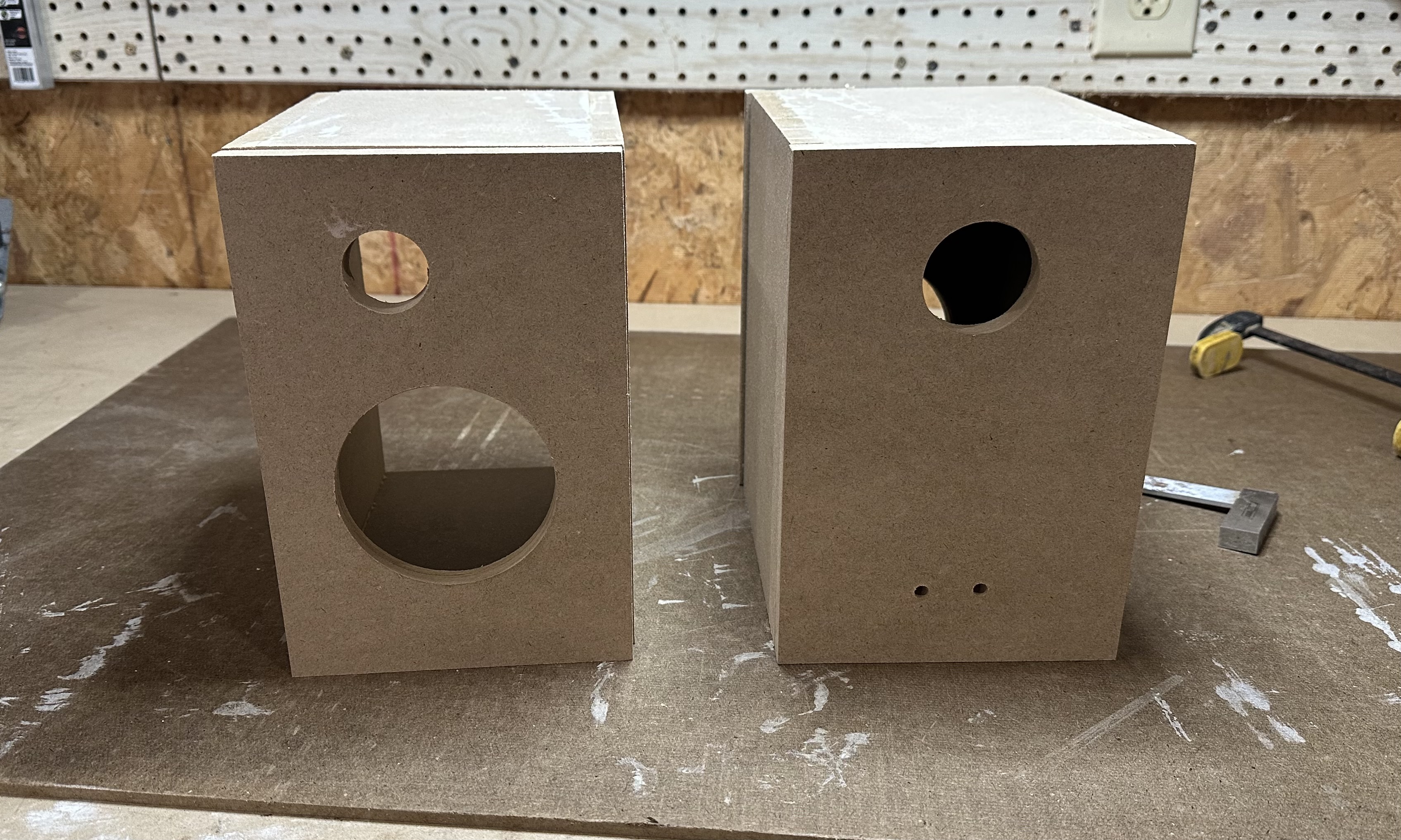
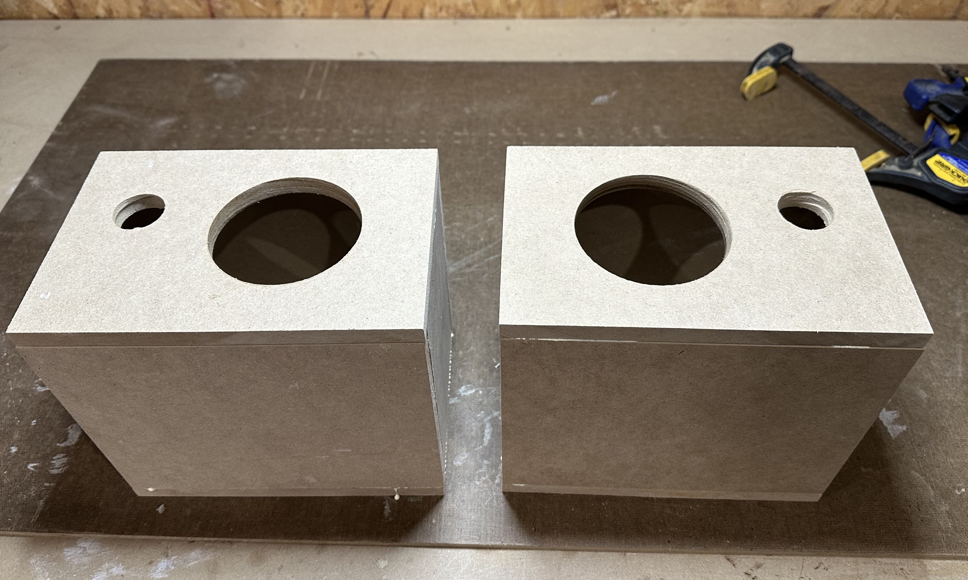
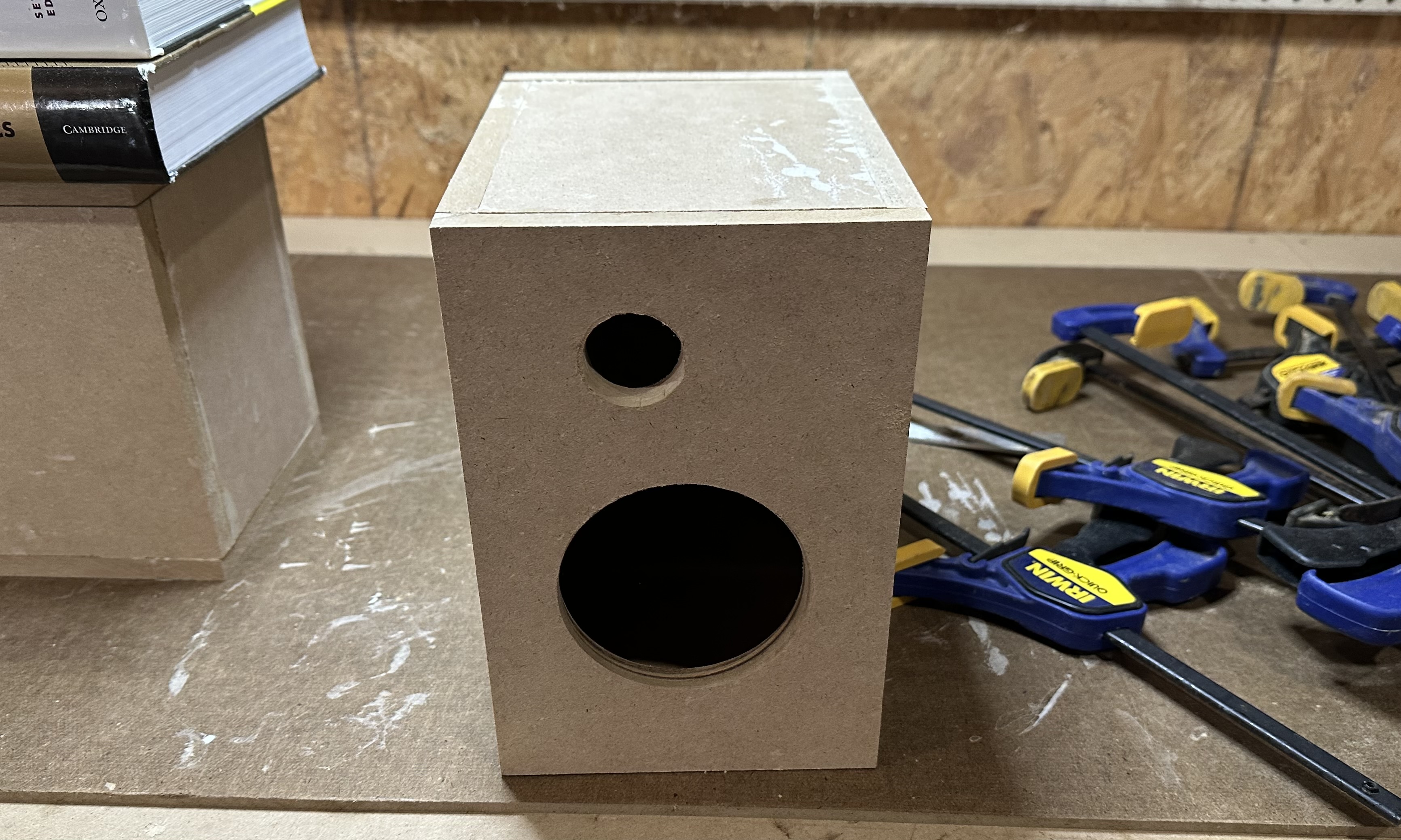
- Test fit the front and back panels. Note the arrangement — the larger opening for the mid-range on the front panel should be "down" and the larger opening for the port tube on the back panel should be "up" so that the mid-range and the port tube don't interfere with each other. On one speaker the tweeter opening should be to the left and the other speaker it should be to the right. (This is for aesthetics only.)
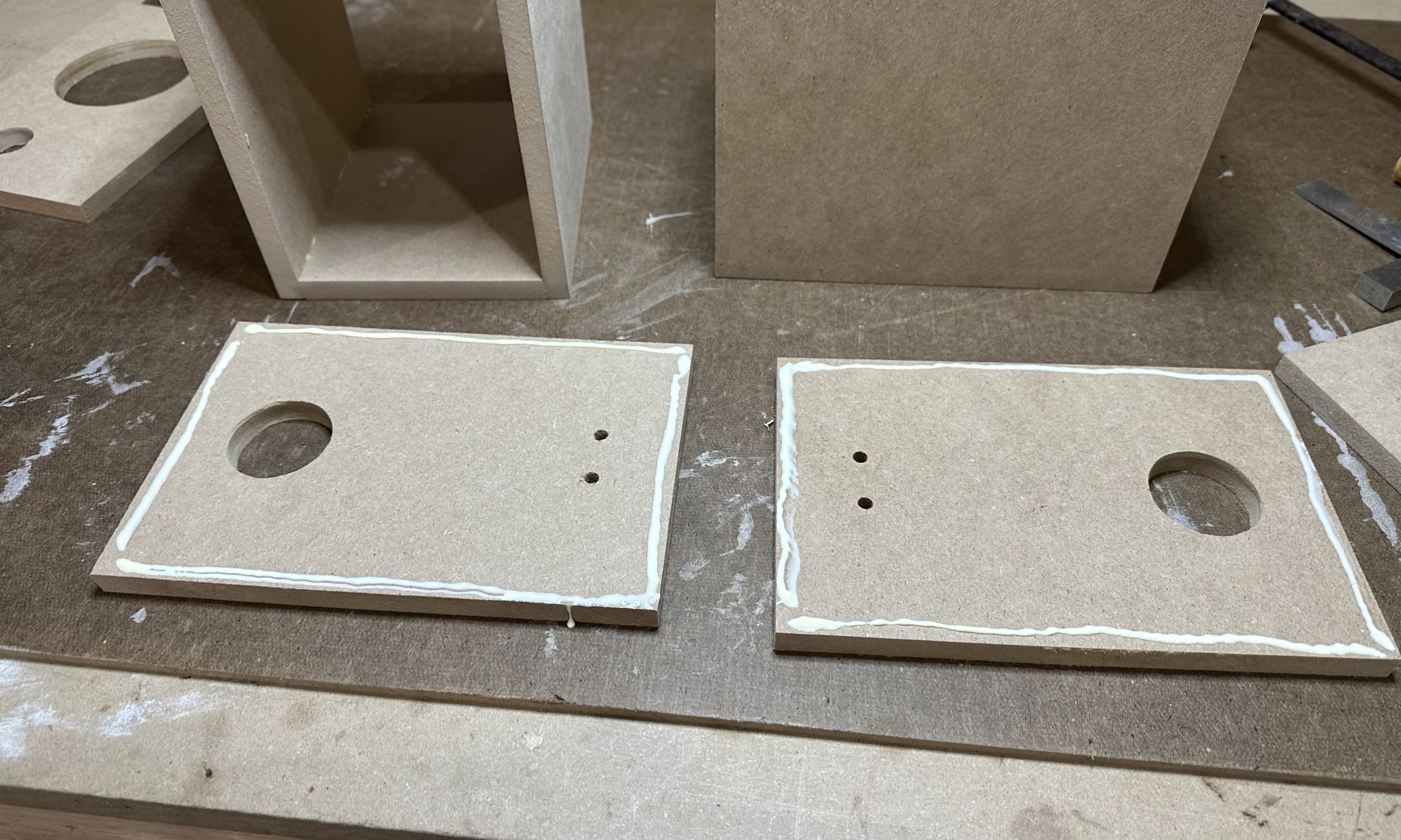
- Lay the back panel flat on the workbench. Apply a thin bead of glue around the outer perimeter.
- Set the box on back panel, with the back edges in the glue.
- Apply a bead of glue to the front edges of the box. Set the front panel on the box.
- If using a weight to hold everything together, place the weight on top now. While the glue is still wet, align the front and back panels to the box as best you can. Be prepared to wipe up excess glue that is squeezed out of the joints as pressure is applied.
- If using clamps to hold everything together, carefully set the box up so that it is sitting on its bottom. Apply the clamps and partially snug them down. Make adjustments to the front and back panels so that they are aligned to the box as best you can. Then tighten the clamps down all the way. Be prepared to wipe up excess glue that is squeezed out of the joints as pressure is applied.
- Check the alignment one last time. Then let the glue dry for at least 30 minutes.
- After the glue has dried, remove the weight or the clamps. Inspect all of the glued joints to make sure they are solid
- If you want, use wood filler to fill any cracks in the joints. Sand everything so that all of the surfaces and corners are smooth. Then paint or finish the exterior to suit your fancy.
Part 2 — Cross-over circuits
If you've built any of the other club projects, soldering together the cross-over circuits should be a piece of cake. The only difference is that the components for the Carmody circuit are quite a bit larger that most of the things we have worked with in the past. Note that you will need two complete PCBs, one for each speaker.
Special note for Fall 2025 builders: I made a slight change to the PCBs for this semester. Instead of one 2-position terminal block and one 3-position terminal block used in the previous version, the current version uses three 2-position terminal blocks. Some of you will have the older version and some the newer version. The two versions function identically. The only difference is during the final assembly when connecting the PCBs to the speaker drivers.. The photos used below were taken using the older version, so the instructions and the photos may not match exactly.
Carmody version
- Assemble the parts for one circuit. (As noted above, if you are building with the newer PCB version, you will have three 2-position terminal blocks.)
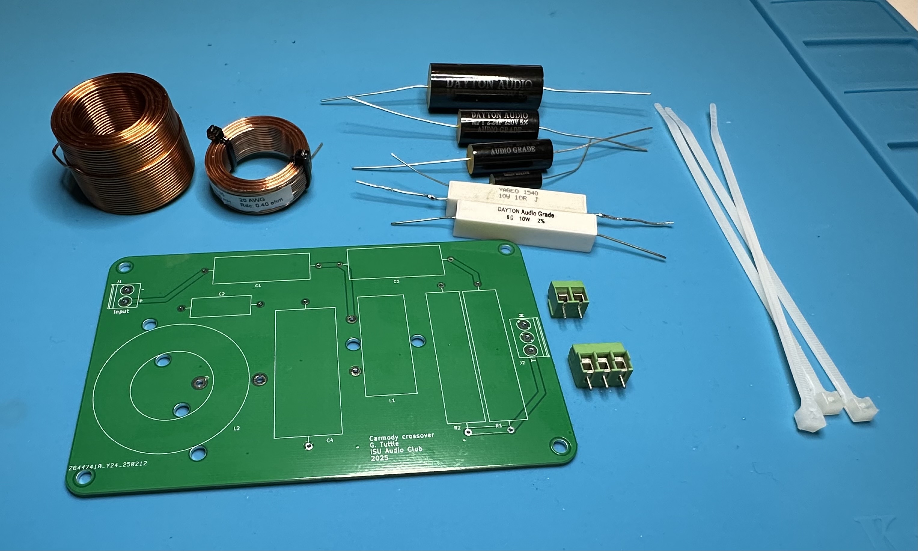
- Solder the two big resistors. R1 is 6 Ω and R2 is 10 Ω — don't mix them up.
- Next, add the terminal blocks. (Two blocks if using the older version, as shown in the photo below or three blocks if using the newer PCB.)
- Now add the four big capacitors. C1 is 1.5 μF, C2 is 0.22 μF, C2 is 2.2 μF, and C4 is 6.8 μF.
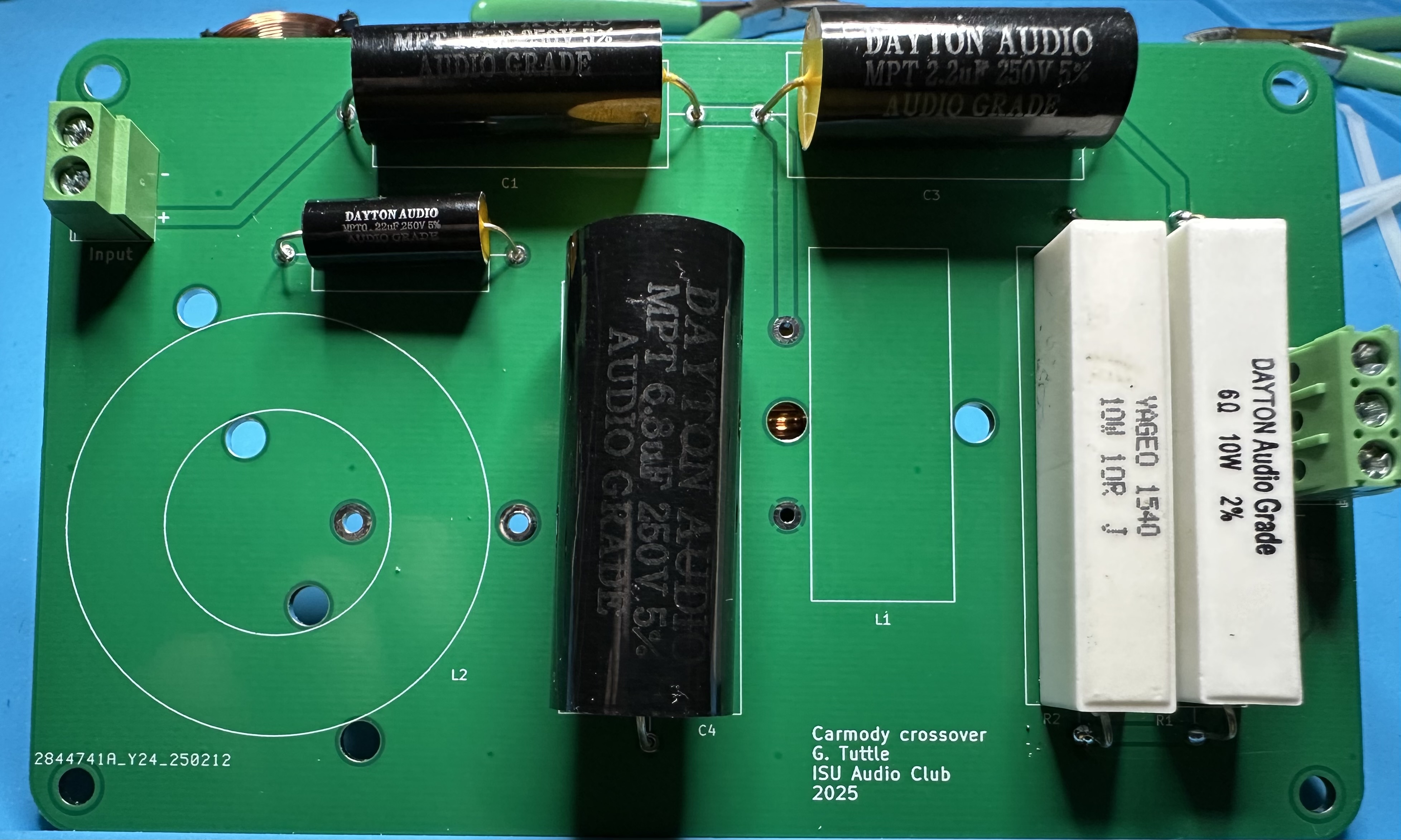
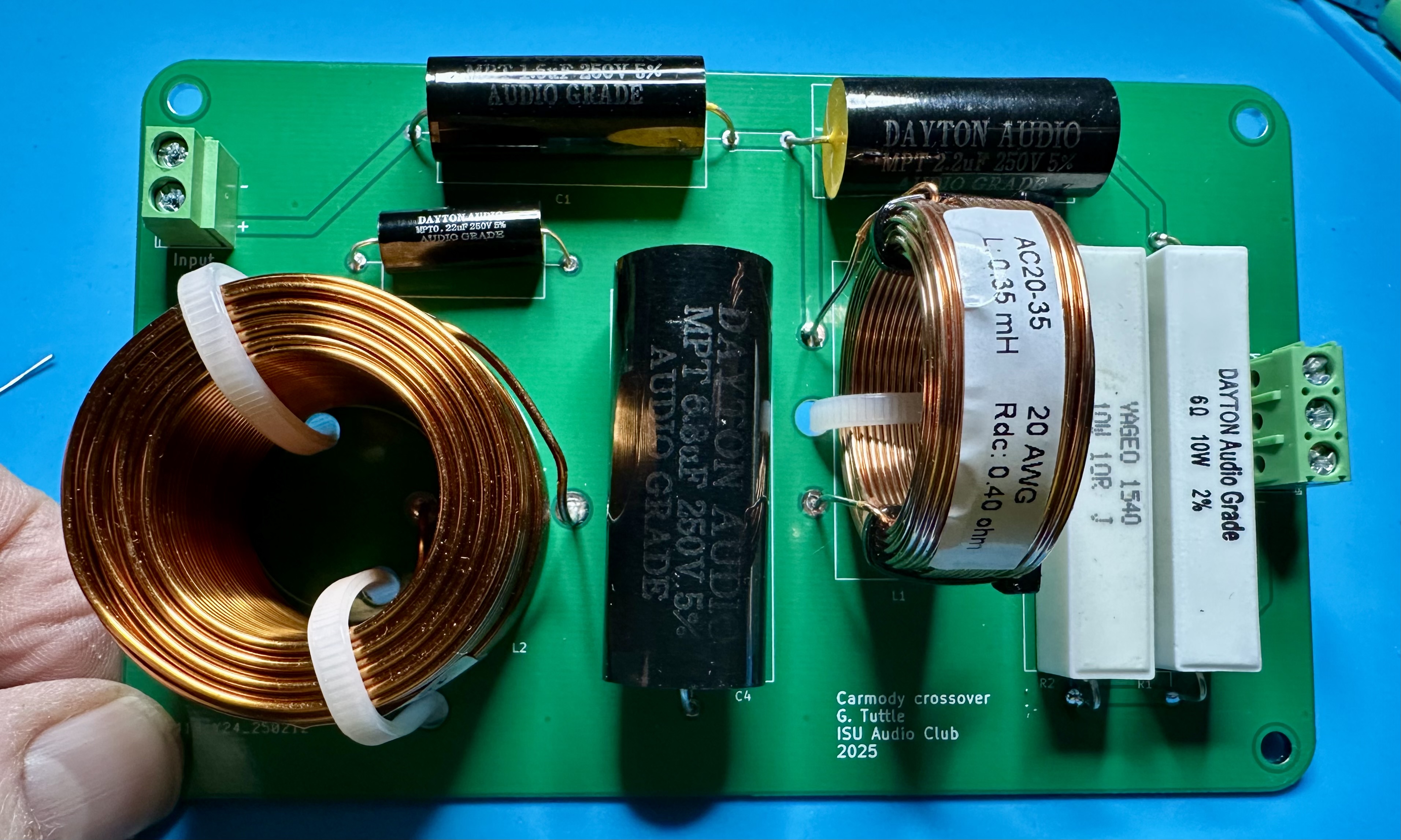
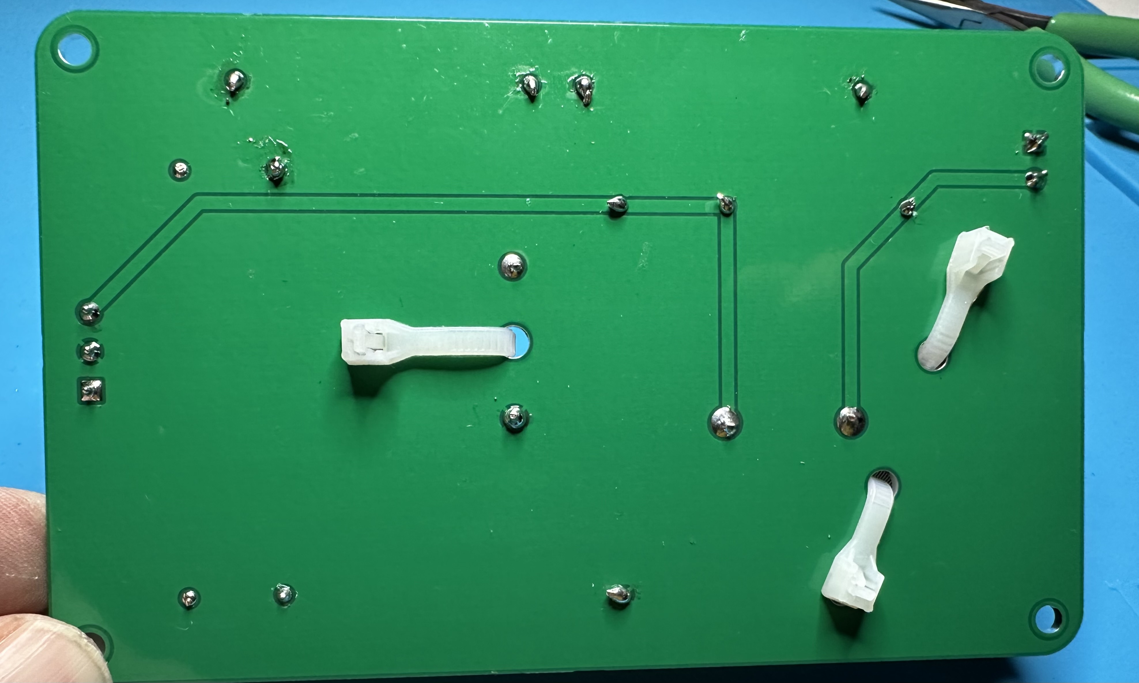
- The big inductors should be secured to the board with cable ties. Thread the cable tie from the back, around the inductor, and back through the second hole. Cinch them up on the back. Then solder the leads in place. Finally, trim off the excess length on the cable ties.
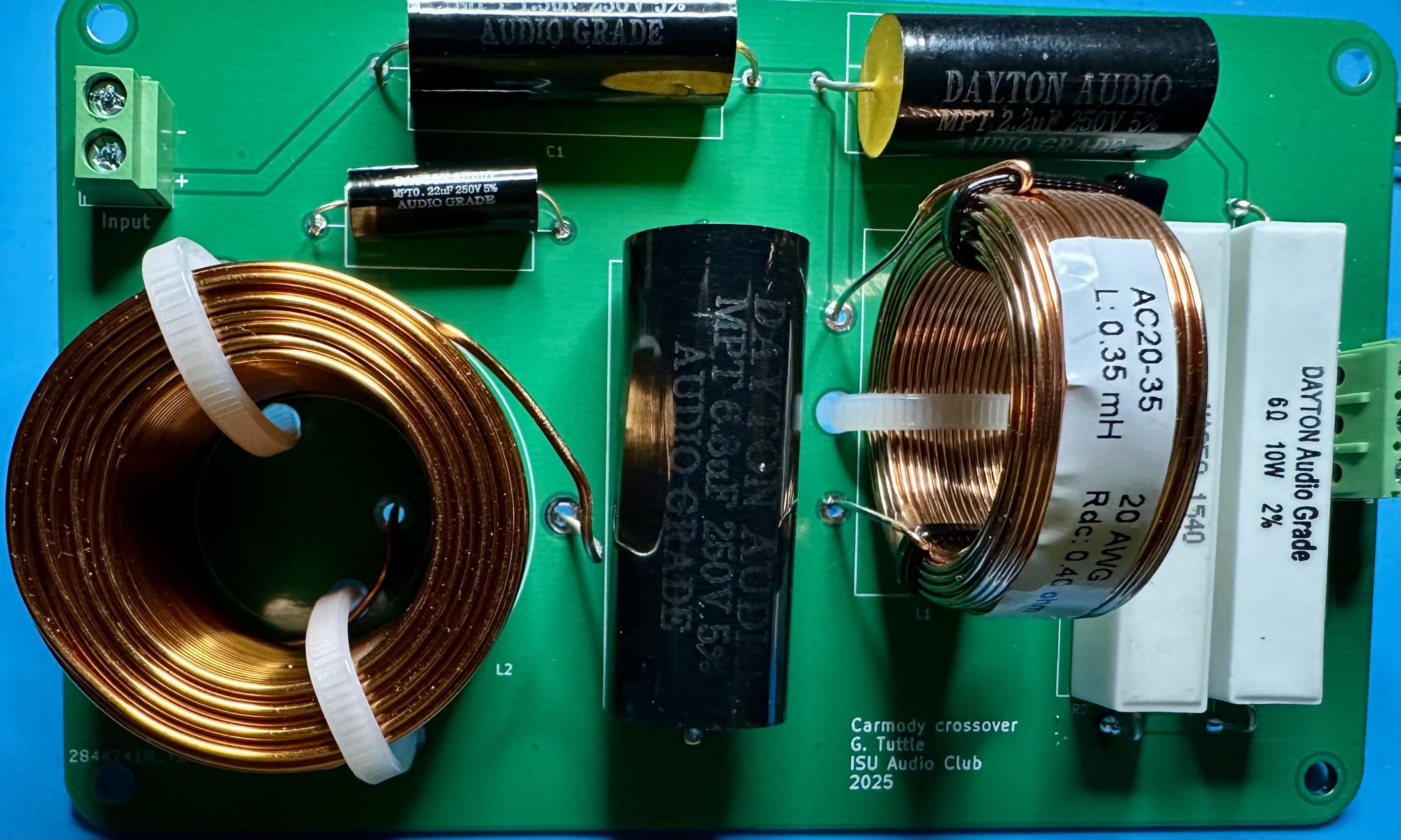
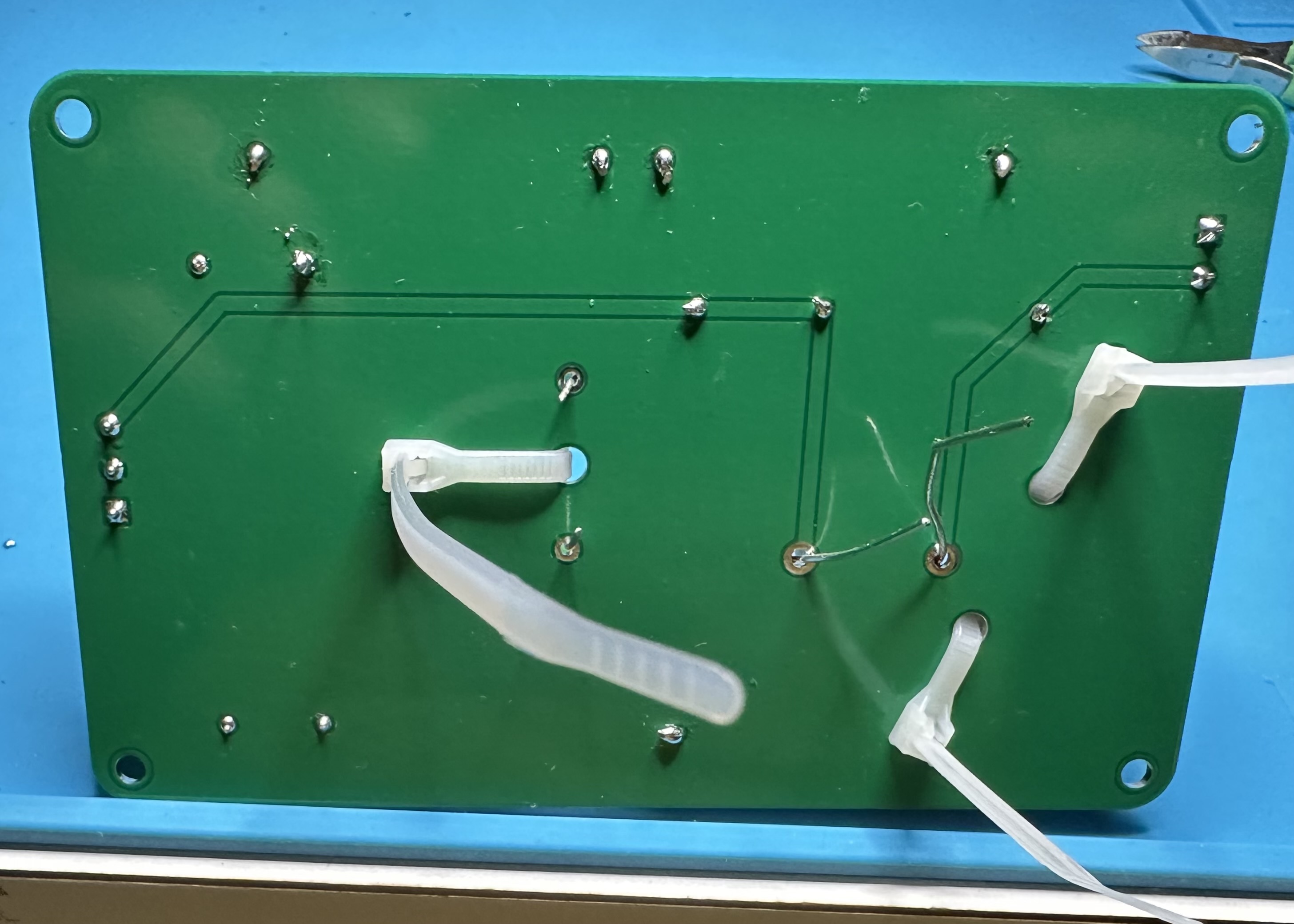
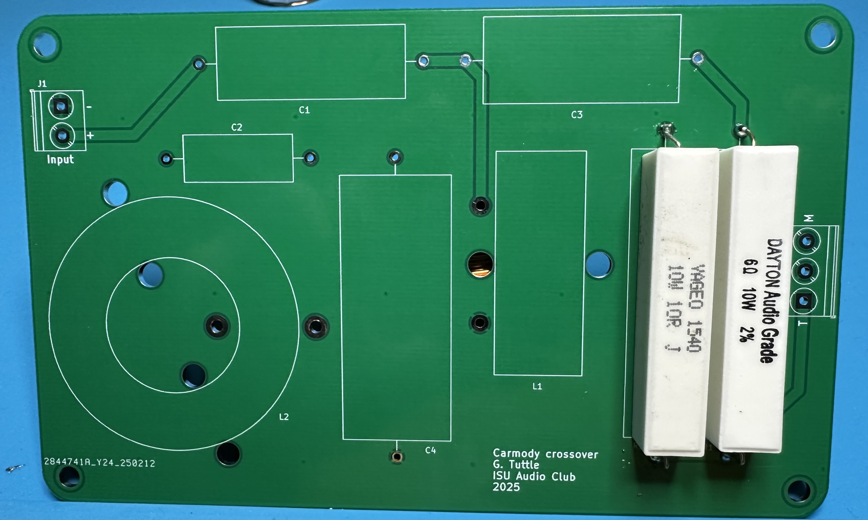
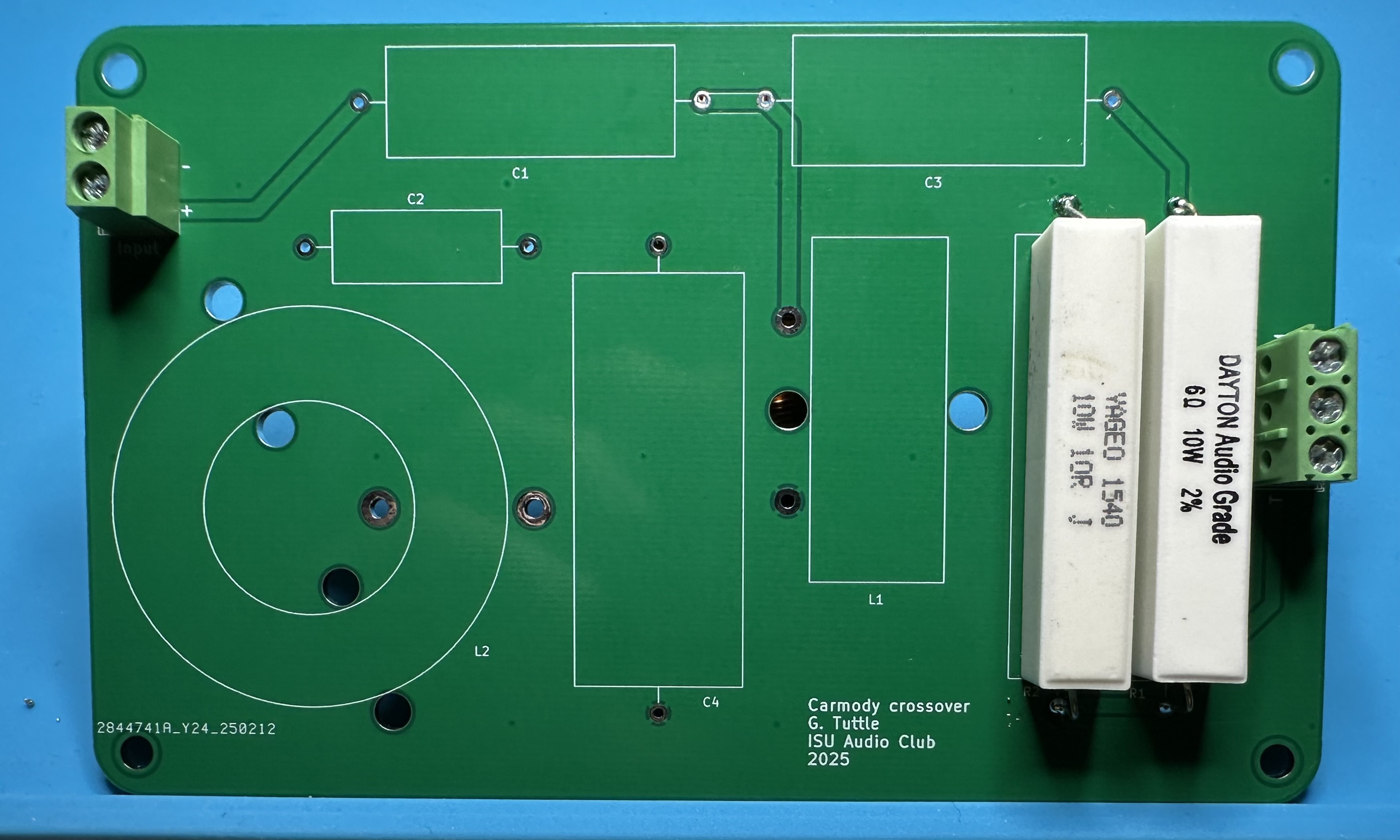
- That's it! Front and back photos of the completed board are shown below. Now repeat the process for the other cross-over.
Economy version
- Assemble the parts for one circuit. (As noted above, if you are building with the newer PCB version, you will have three 2-position terminal blocks.)

- Solder the two big resistors. R1 is 6.2 Ω and R2 is 10 Ω — don't mix them up.

- Next, add the terminal blocks. (Two blocks if using the older version, as shown in the photo below or three blocks if using the newer PCB.)

- Now add the four capacitors. C1 is 1.5 μF, C2 is 2.2 μF, C2 is 0.22 μF, and C4 is 6.8 μF.

- Finally, solder in the big inductors. Solder L1 with the leads extending a bit so that the inductor can be bent over as shown in the photo. The horizontal orientation minimizes magnetic coupling to L2.

- That's it! Now repeat the process for the other cross-over.
Part 3 — Final assembly
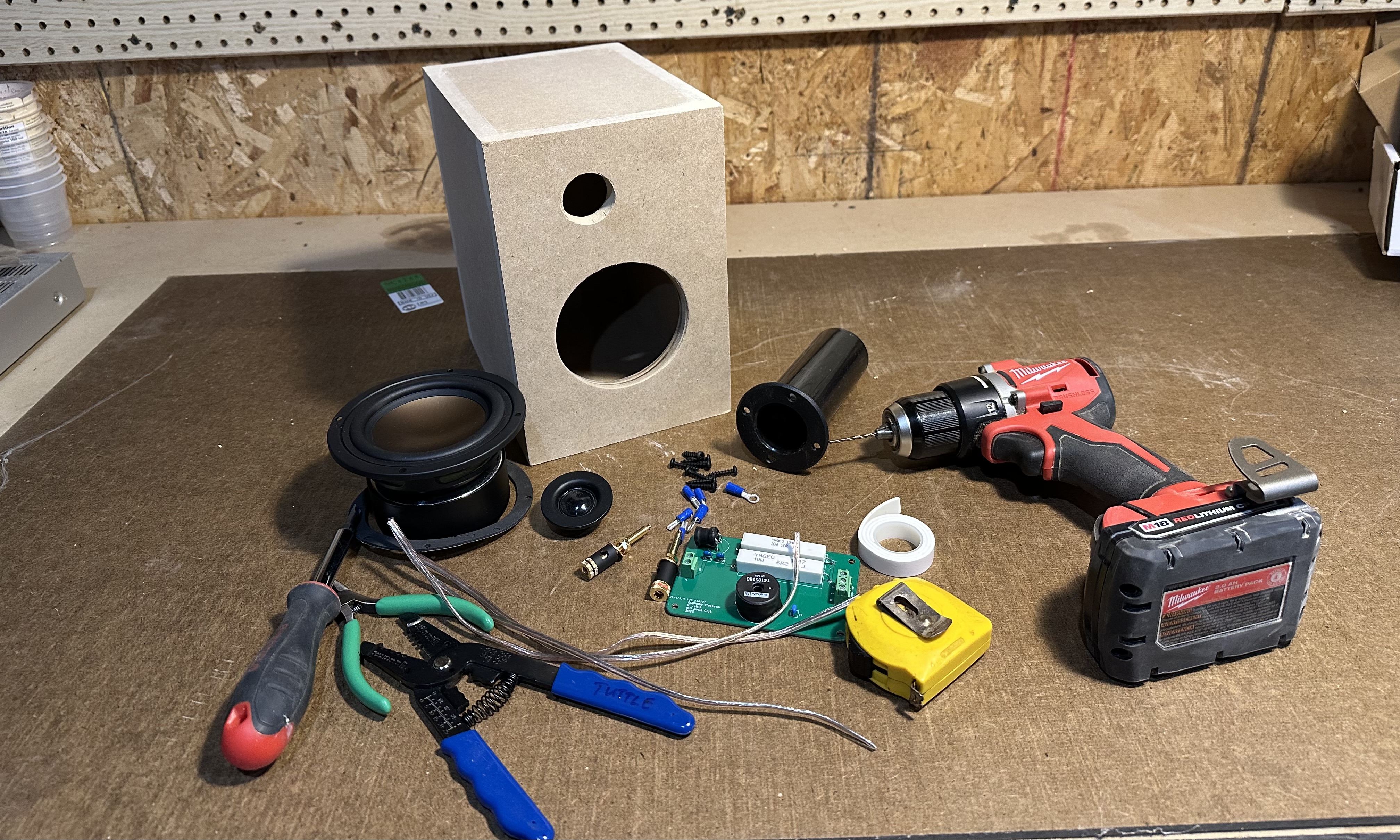
- Gather together all the parts and tools that will be needed
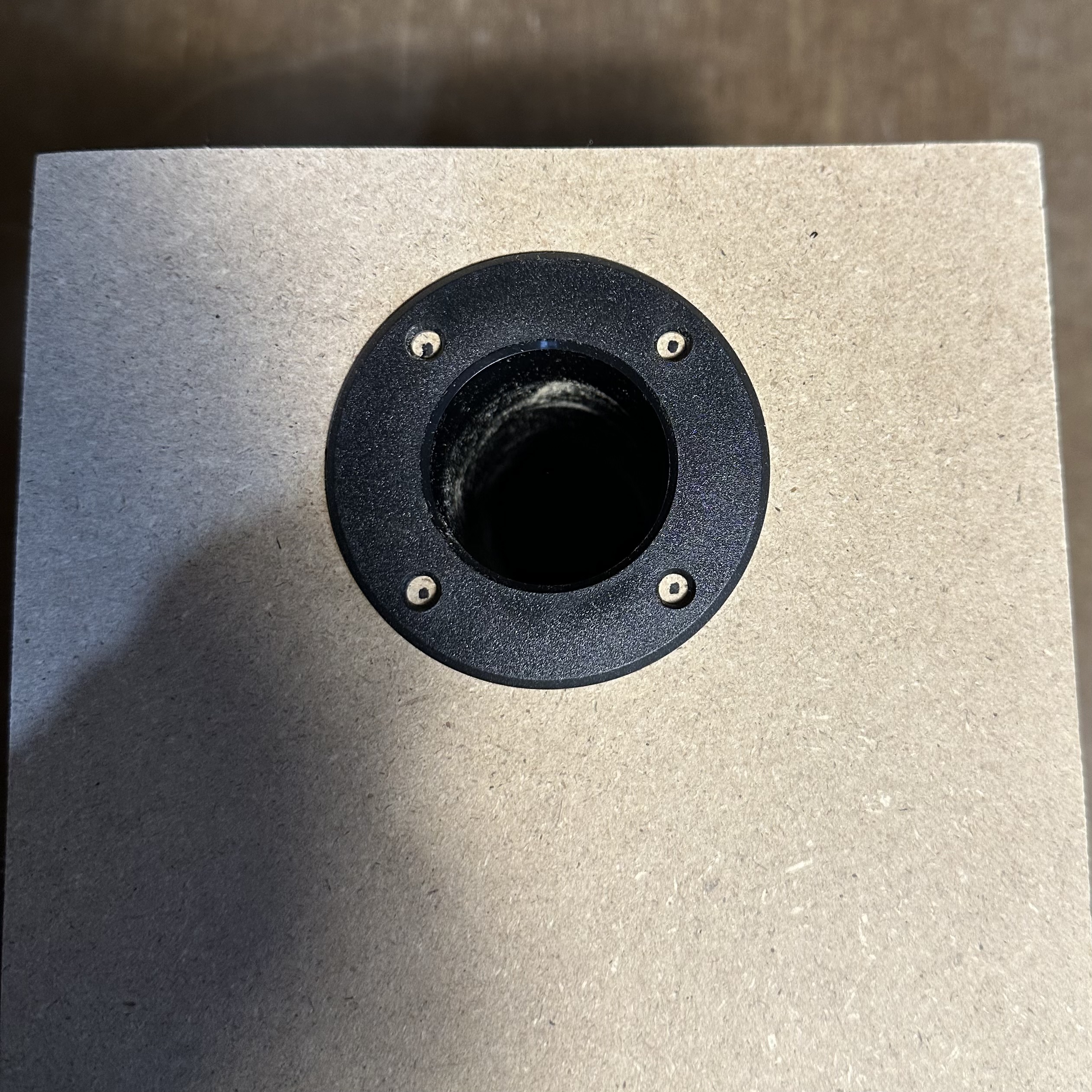
- Test to make sure that the outer portion of the port tube fits through the port hole in the back. If the hole is too small, use sandpaper or a Dremel tool to make the hole a bit bigger
- Do the same for the tweeter. This should be a tight fit, but if the tweeter hole is too small, enlarge it until the tweeter just fits.
- Insert the outer port tube through the port hole and mark four locations for the four mounting holes. Do the same for the mid-range driver on the front.

- Drill pilot holes using a small bit, maybe 3/32 or 5/64.

- Remove any dust or debris from inside the box. Use a vacuum or wipe it out thoroughly with damp rag. Wipe the bottom of interior to make sure that all dust is gone. Any dust will make it so that the double-sided tape used below will not stick.
- Install the two binding posts — one red and one black. It doesn't matter which is left or right. Put on the washer and then one nut for each. Tighten down them as much as possible with your fingers.

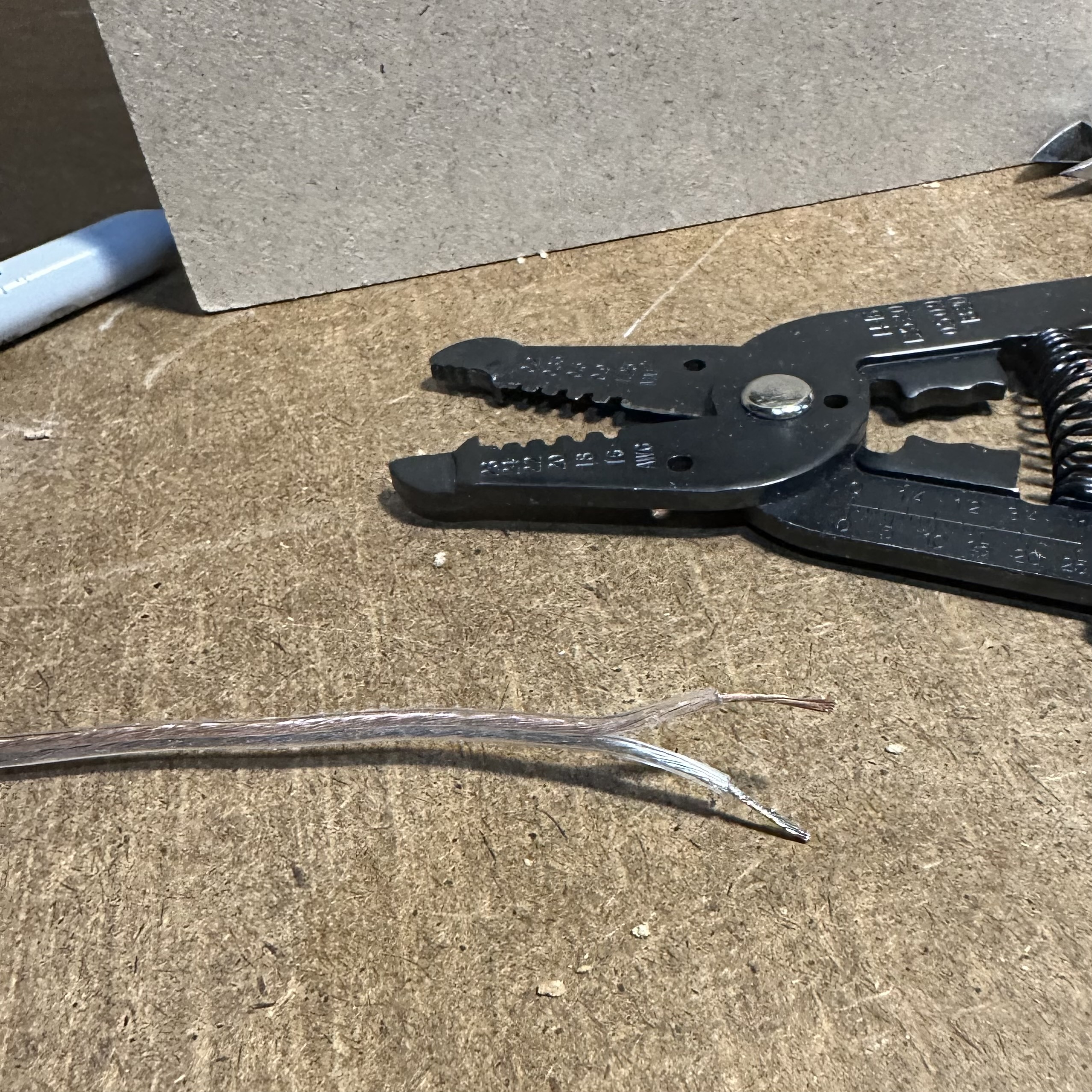
- Use wire cutters (Or a knife, but be careful!) to split the ends of the speaker wire. Peel the two wires apart an inch or so. Then use wire strippers to remove about a half-inch of insulation from each wire.
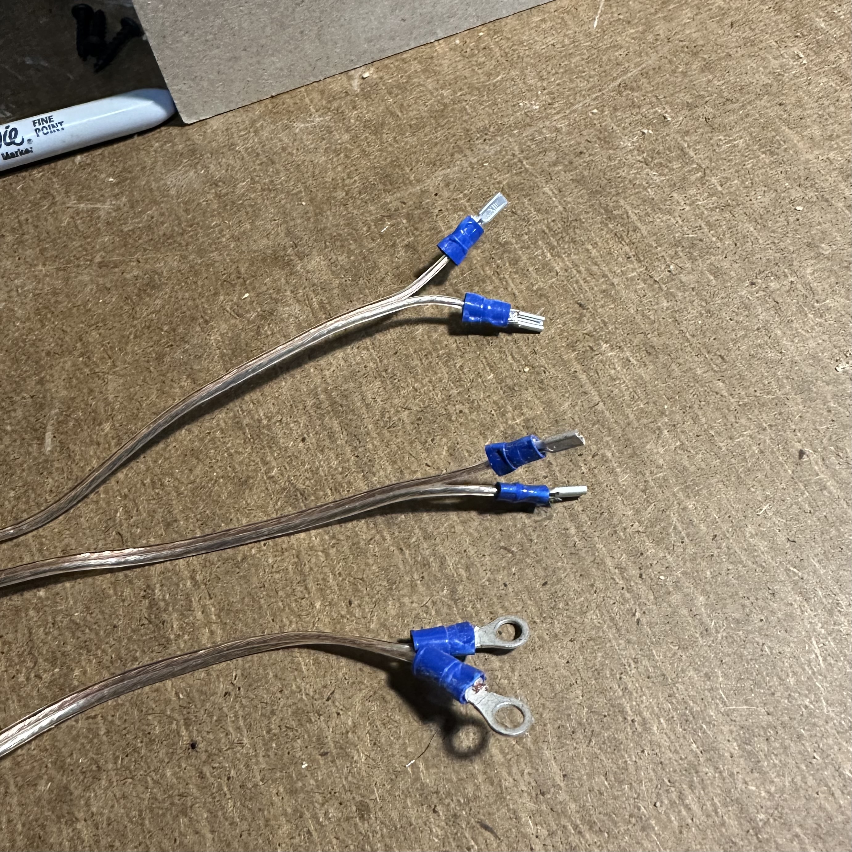
- Attach crimp connectors at one end of each length of wire. One wire will have two ring-type connectors and the other two will have "slide-on" connectors. Crimp the connectors securely! Make sure they are not loose. (If they are loose, ask for new oens and try again.)
- Attach the wires with the ring connectors to the binding posts. Use the second nut and tighten securely. Keep track of how you are connecting wires and be consistent with all remaining connections. In this case, the speaker wire has one copper-colored conductor and silver-colored. We are using the copper-colored wire as the "positive" and the silver as the "negative". The postive is connected to the red binding post and the negative to the black.

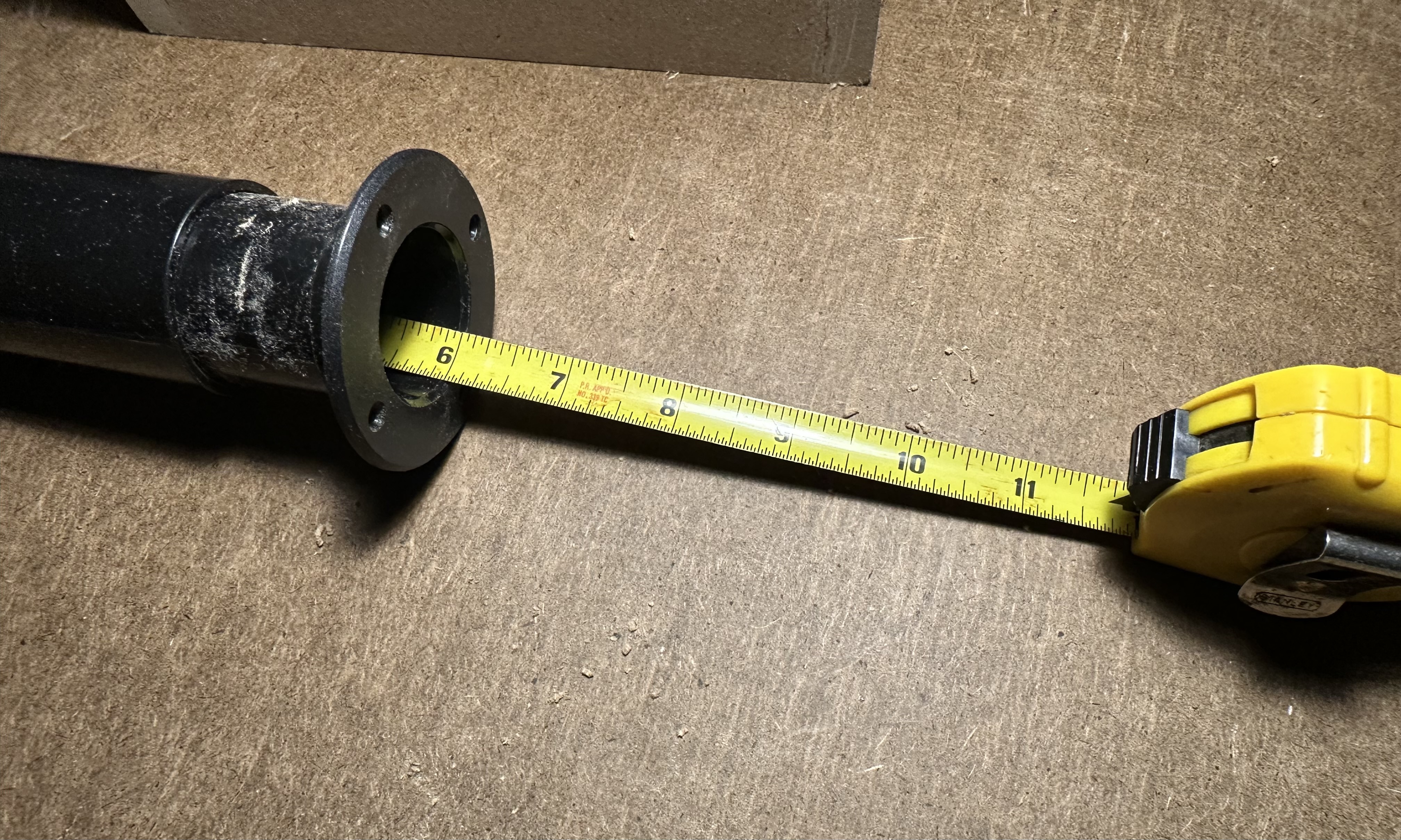
- Put the two halve of the port tube together and adjust the length to six inches from end to end. Secure the two halves together at that length. Use duct tape (Tape all the way around), or glue, or the fancy speaker caulk that GT has available. (As shown here.)

- Slide the port tube into the port opening and secure it in place with four screws.
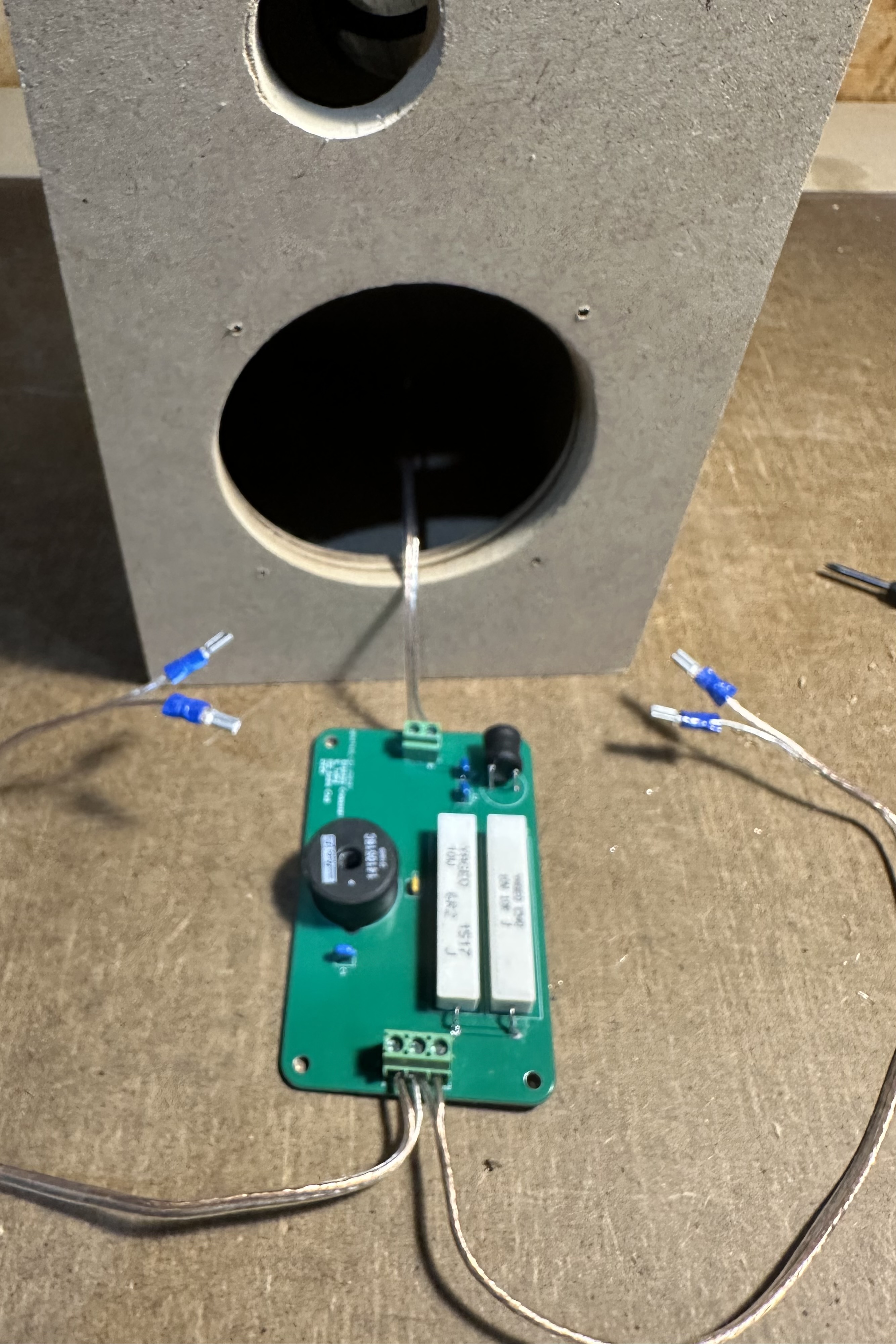
- Attach the speaker wire coming from the binding post to the input of the cross-over circuit. Again, be consistent with postive and negative. Trim the wires so that there will exposed wire at the connector — exposed wires might short together when the wire is flexed.

- Attach the other two speaker wires to the tweeter and mid-range connectors. (If you using one of the older boards that has one three-position terminal block, the center is the negative and the negative side of both speaker wires must go into the one opening.) Again, make sure there is no exposed wire at the connectors. Pay attention to which wire is tweeter and which is mid-range.
- Put several strips of double-sided tape on the back of the PCB.

- Peel off the backing from the tape and stick the PCB to the bottom of the box. If the box has dust or debris, the tape will not stick well!

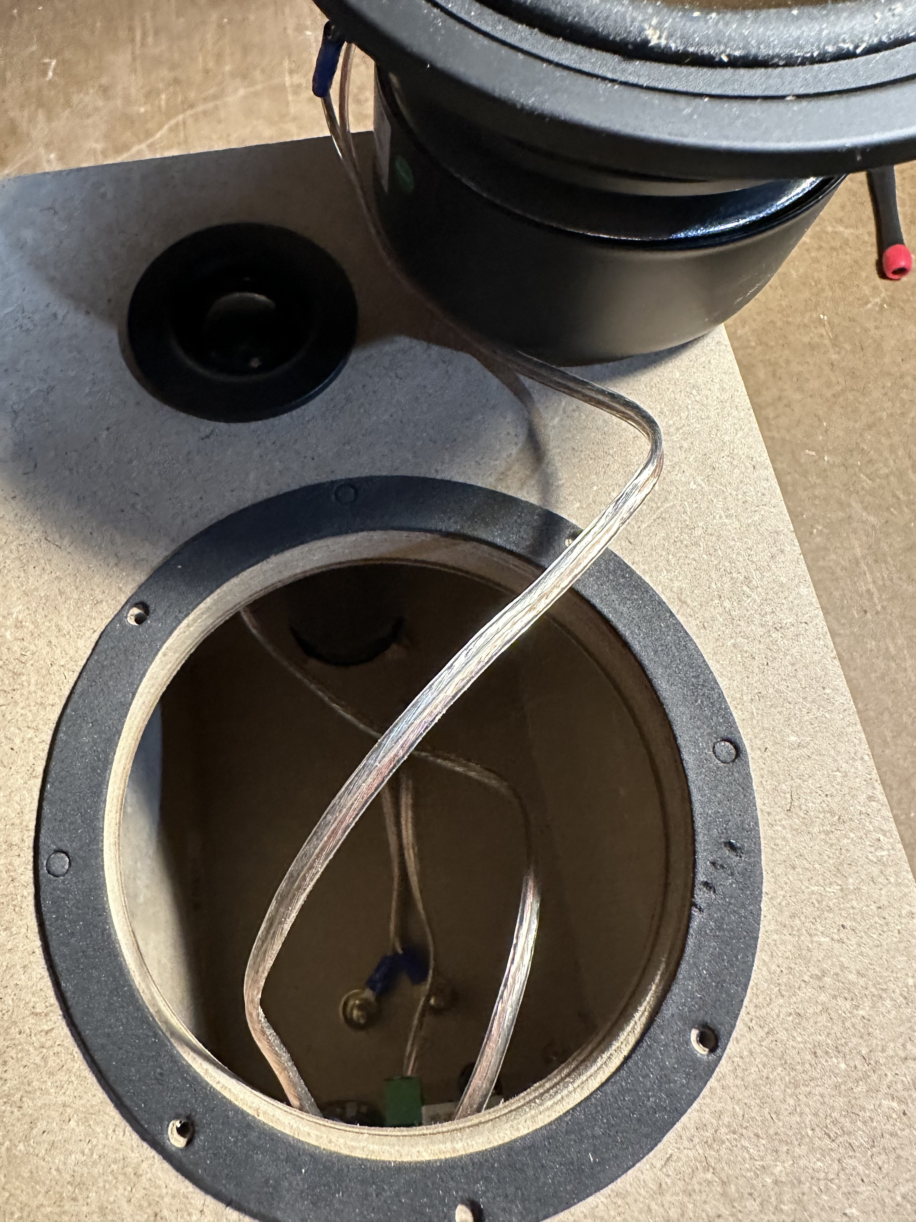
- Put the tweeter wire through the tweeter hole and attach the wire with the slide-on connectors. (Red is positive.) Install the tweeter into its opening. If the tweeter does not fit tightly, it may be necessary to add a couple of drops of glue.

- Put the midrange wire through the midrange hole. Set the gasket (paper side up) on the midrange and attach the wire with the slide-on connectors. (Again, red is positive.) Install the tweeter into its opening. If the tweeter does not fit tightly, it may be necessary to add a couple of drops of glue.

- Set the speaker on its back. Remove the paper from the gasket and stick it down so that four of the holes align with the holes drilled earlier. Set the mid-range into the opening and install four screws to secure it.
- Done with one. Now repeat everything for the second speaker.