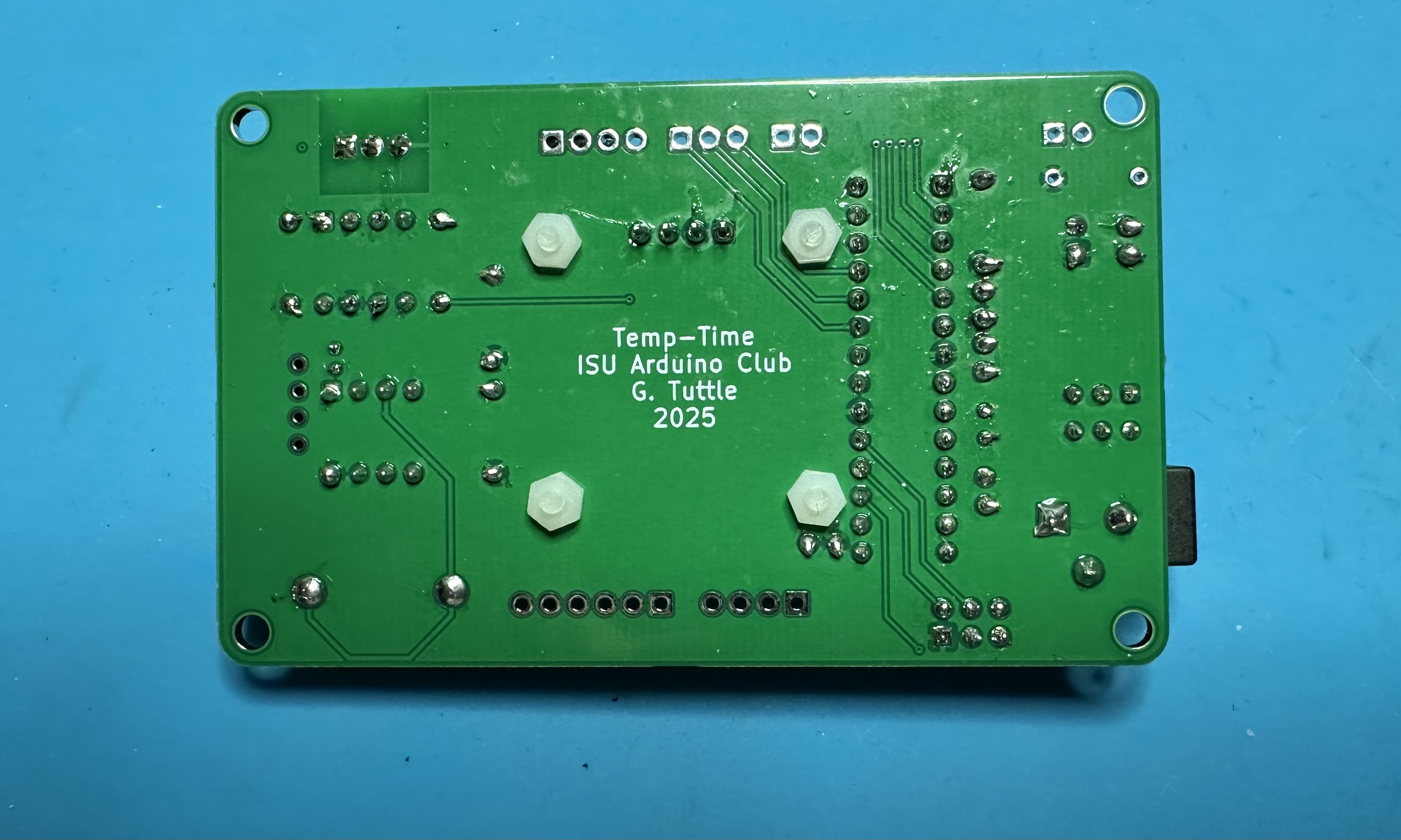
ISU Audio and Arduino Club
Temp-Time build instructions
Below are steps for building the Temp-time project.
For anyone who has made any of the earlier Arduino projects, this build should be familiar. Of course, there are extra components that provide the time and temperature functionality and the display.
The order of assembly given below is a suggestion, but there is nothing wrong with soldering the parts in a different order.
The usual tools are required: solder and soldering iron, needle-nosed pliers for manipulating parts and pulling leads, and wire cutters for trimming leads after soldering. Helpful but not essential would be a vise for holding the boards, a magnifying glass and light for viewing small print, and tweezers for holding the surface-mount part in place during soldering.
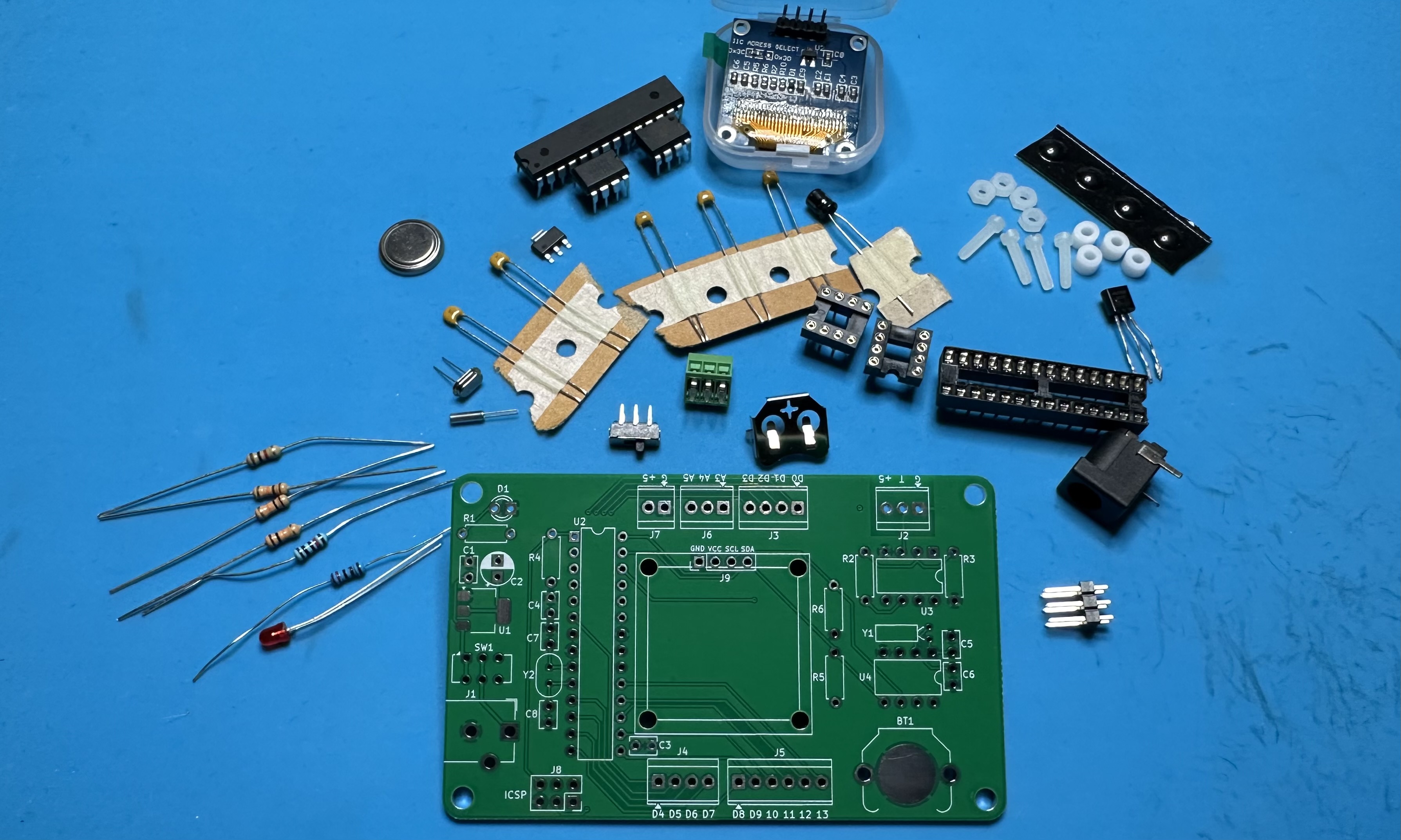
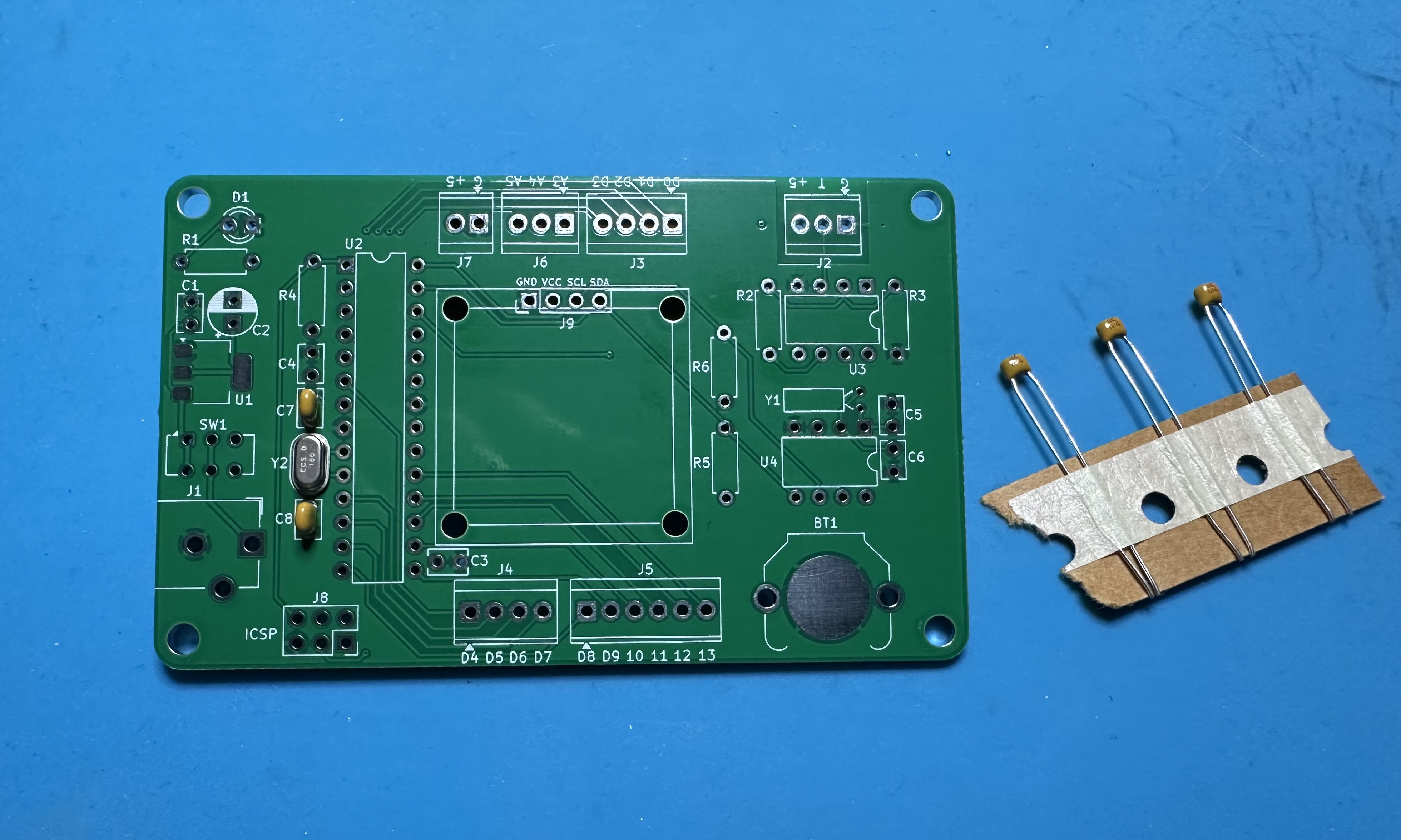
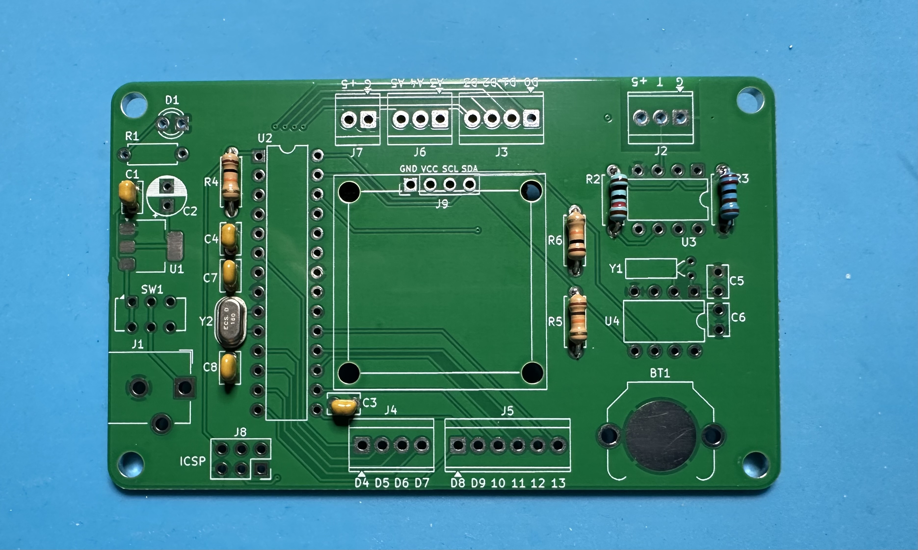
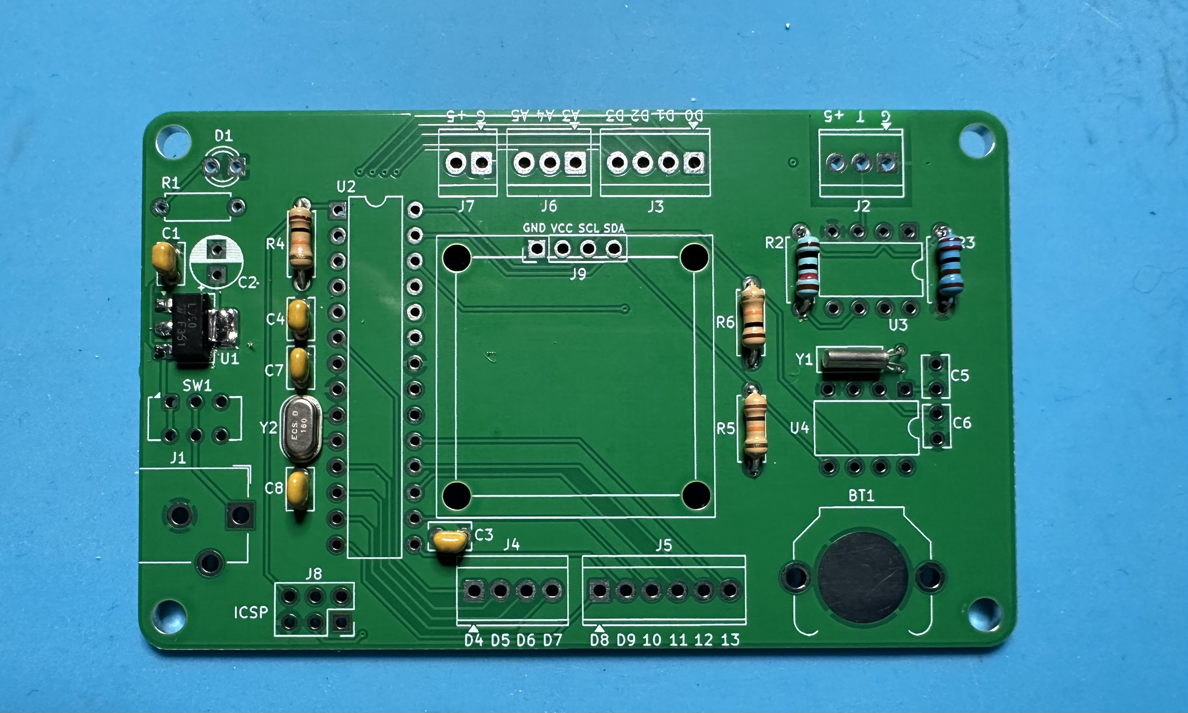
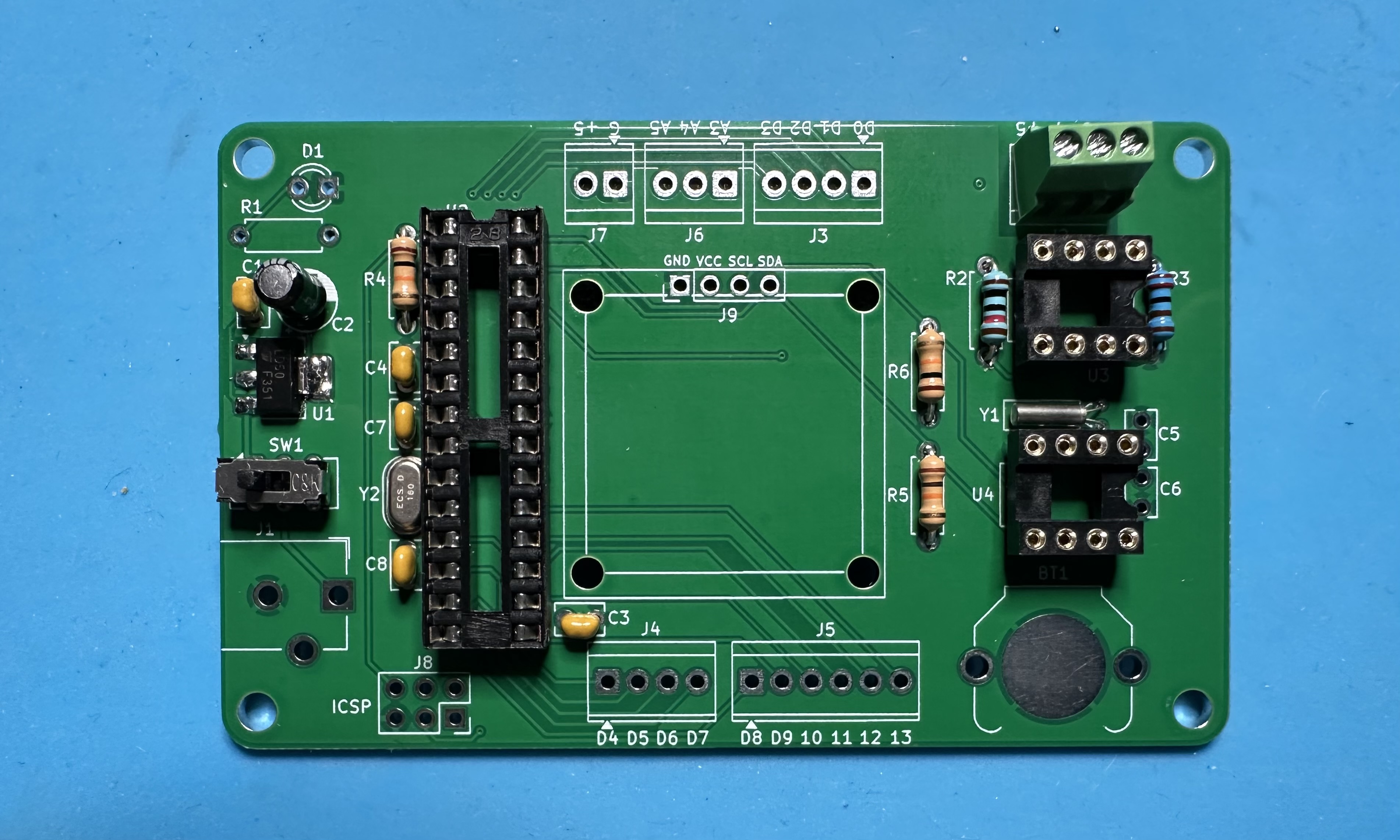
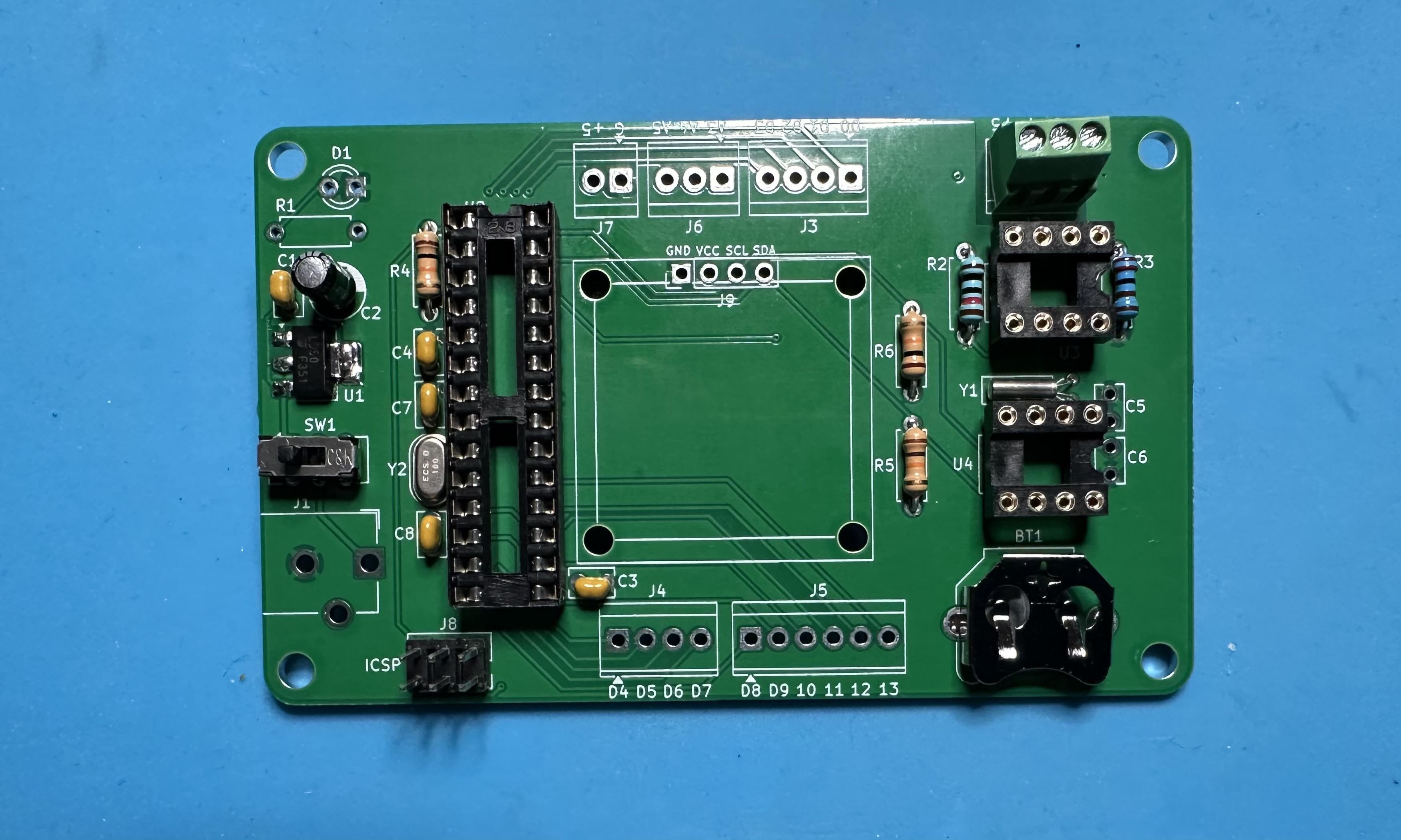
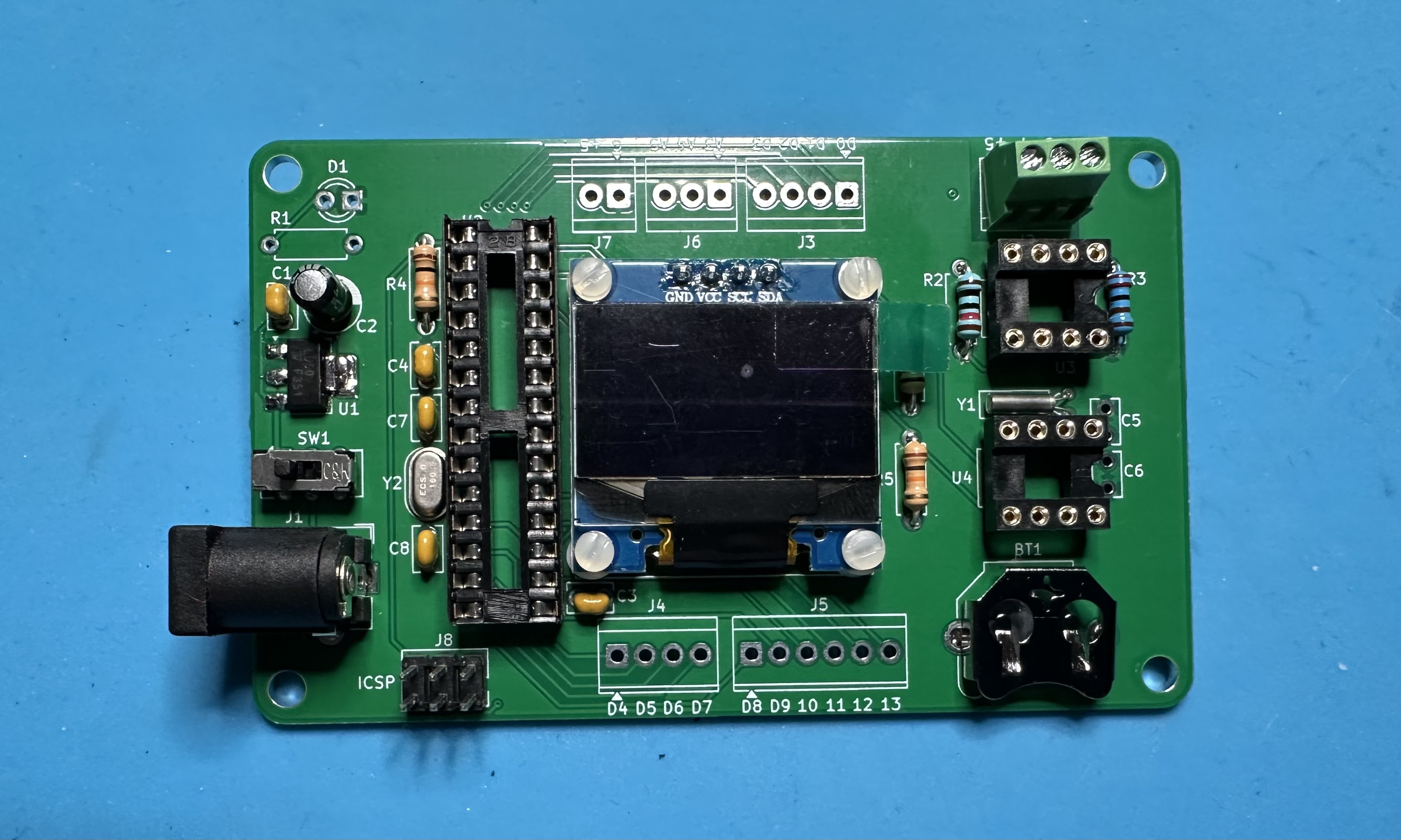
- Assemble the parts. (See the BoM for the complete list.)
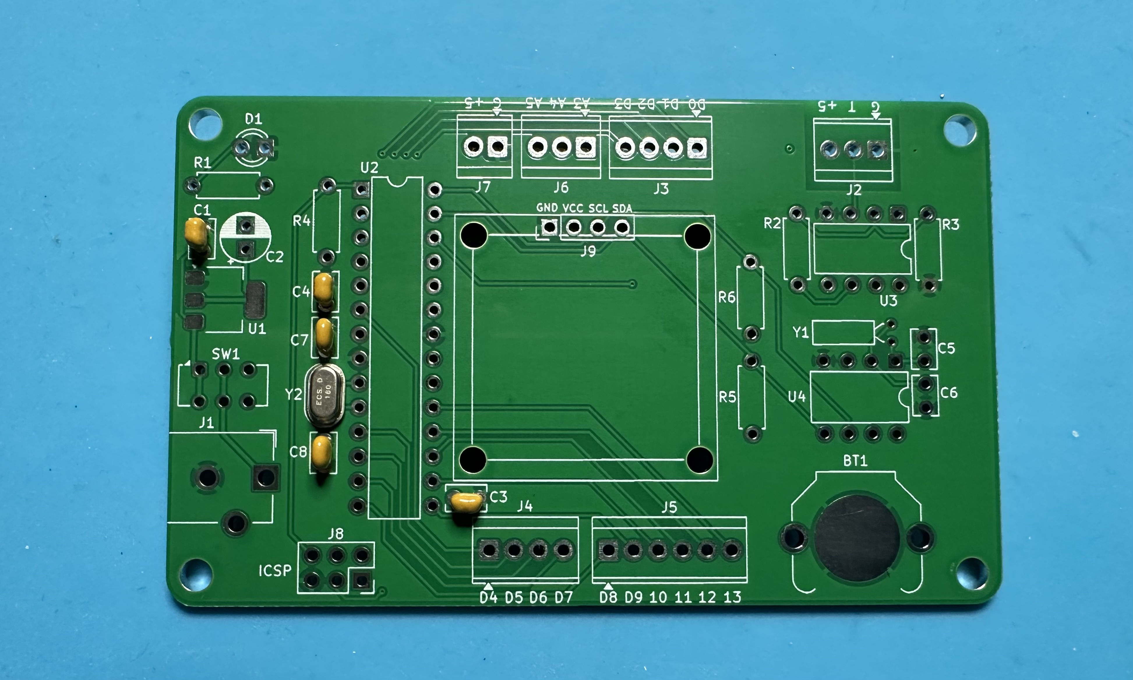
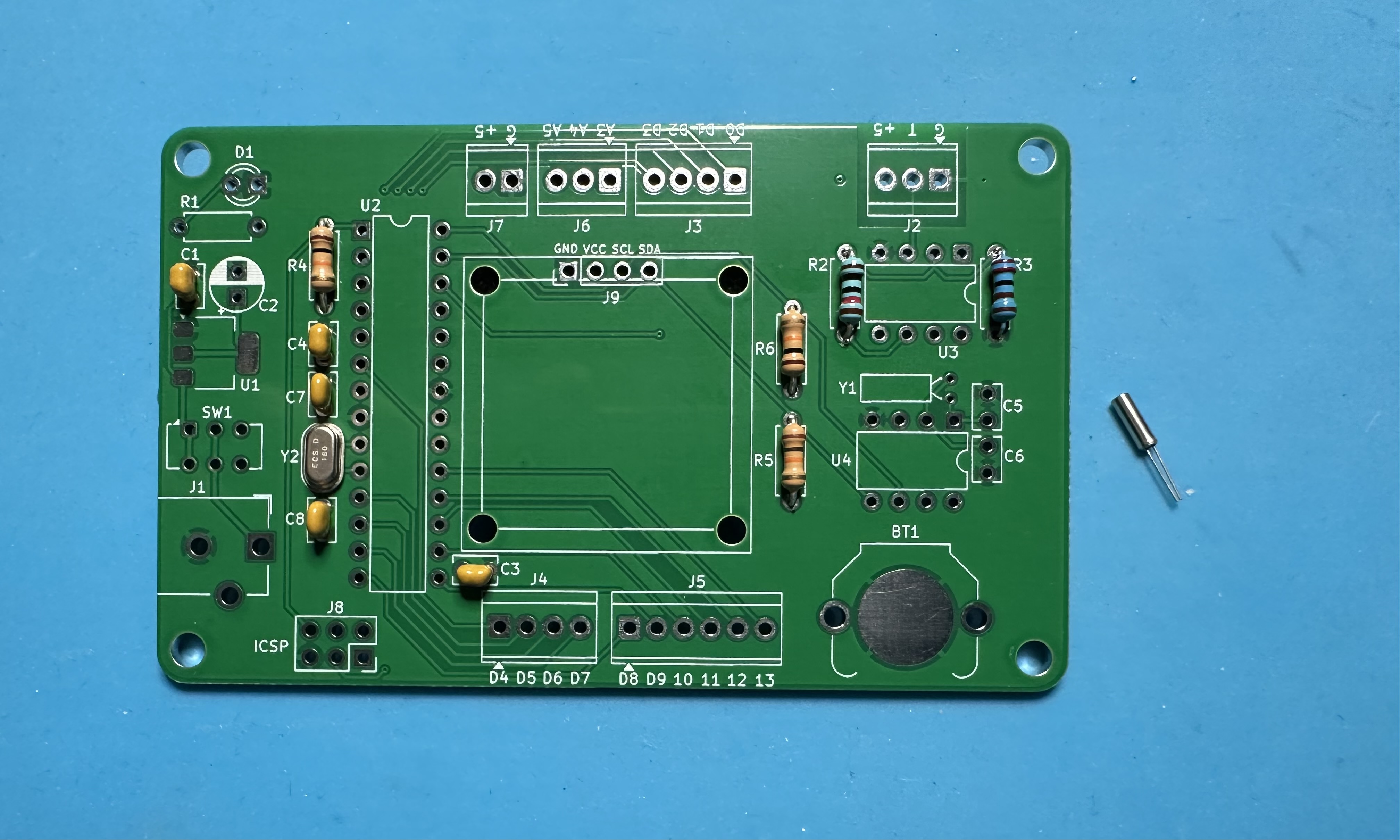
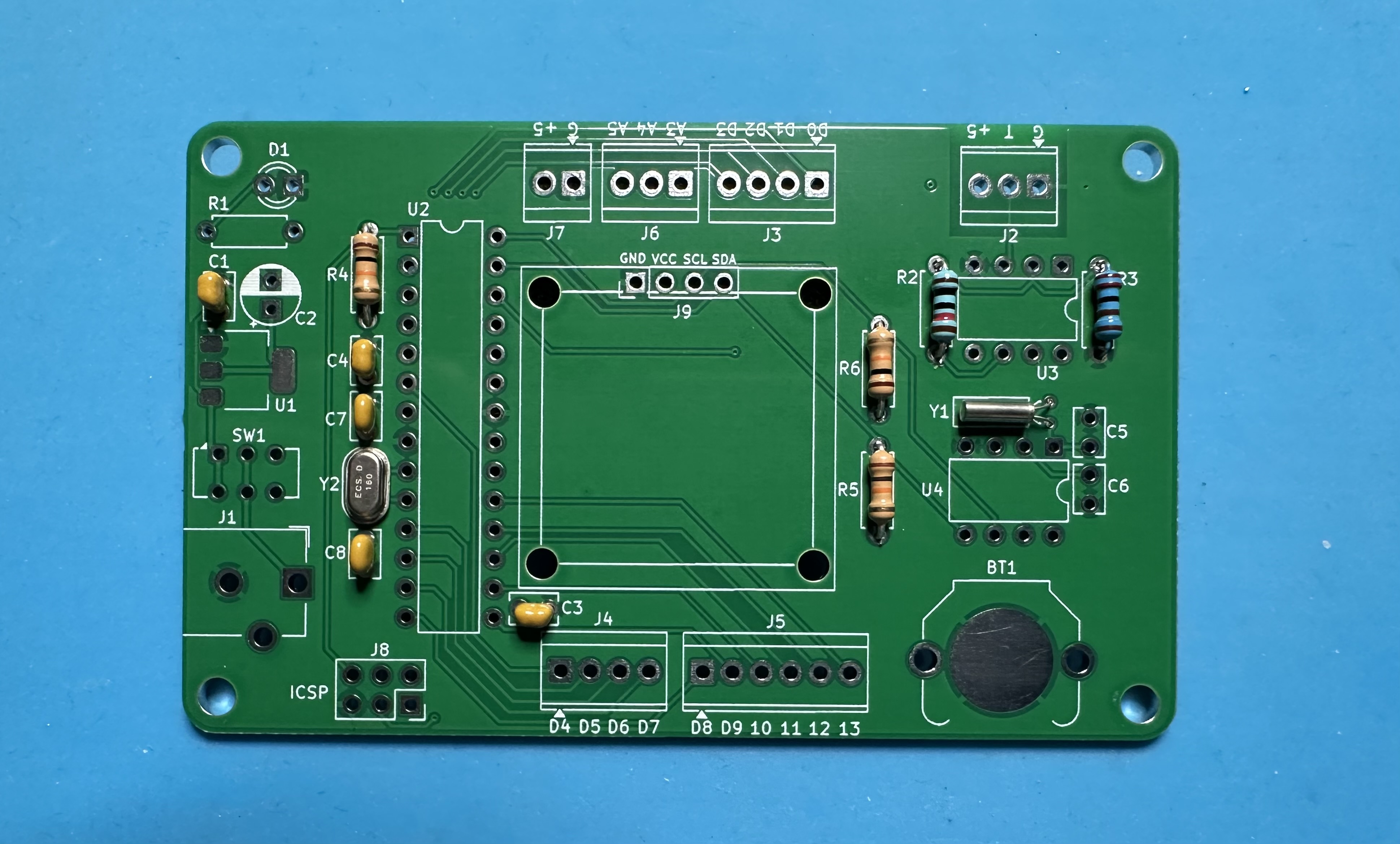
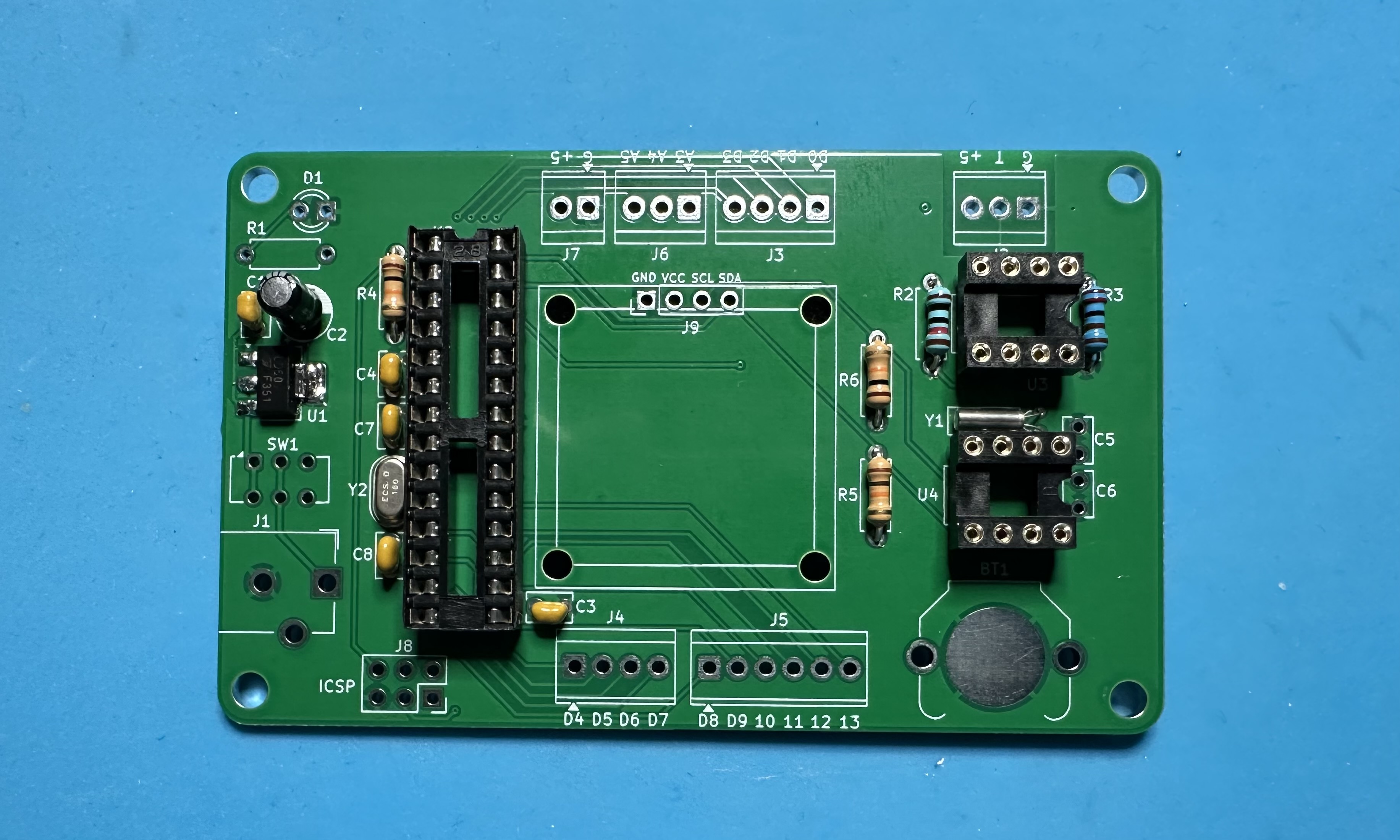
- As usual, we start small and work our way to the bigger parts. Begin with the Atmega 16-MHz oscillator crystal (Y1) and its 22-pF capacitors (C5 and C6).
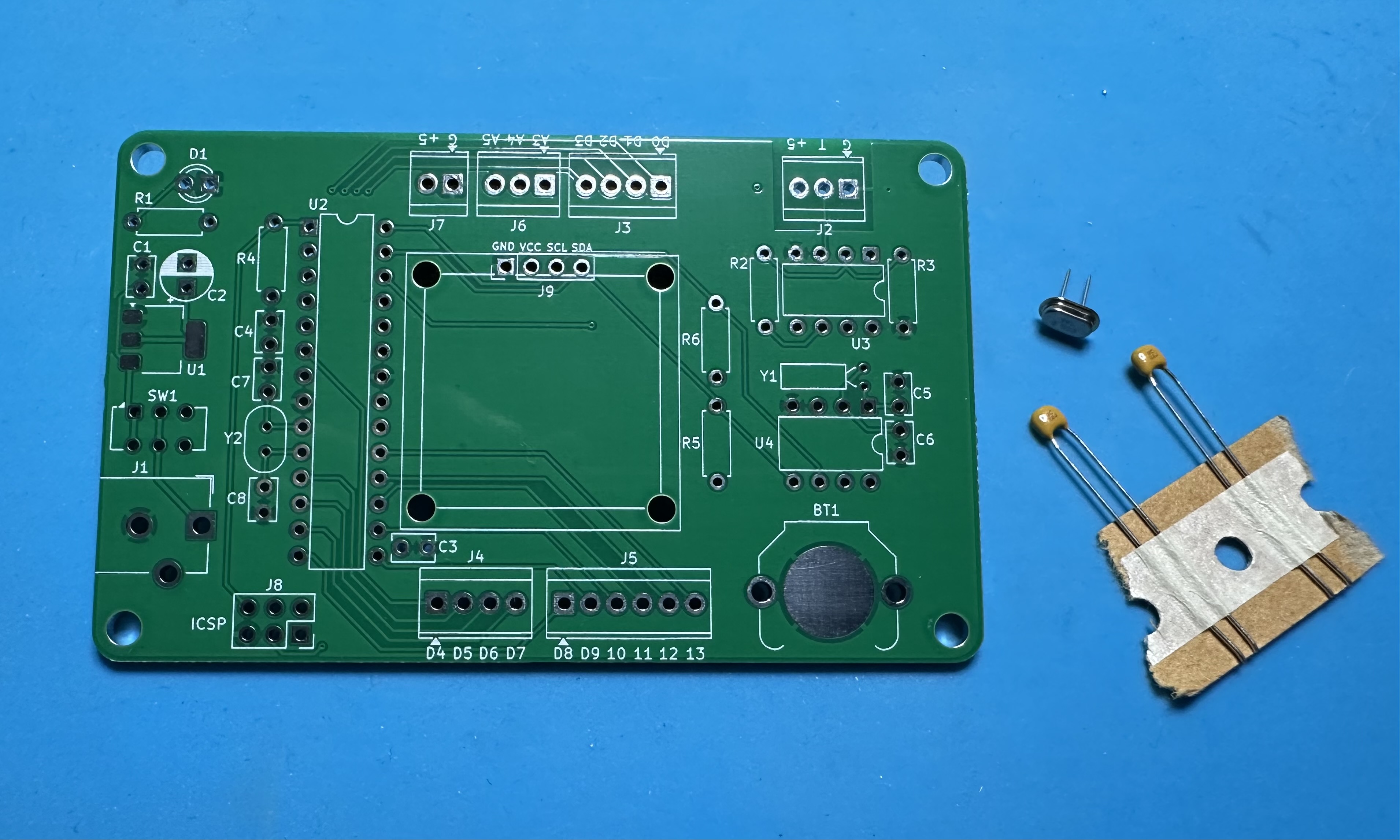
- Three 100-nF (104) capacitors — 2 for Atmega bypassing (C3 and C4) and one for stability of the voltage regulator (C1).
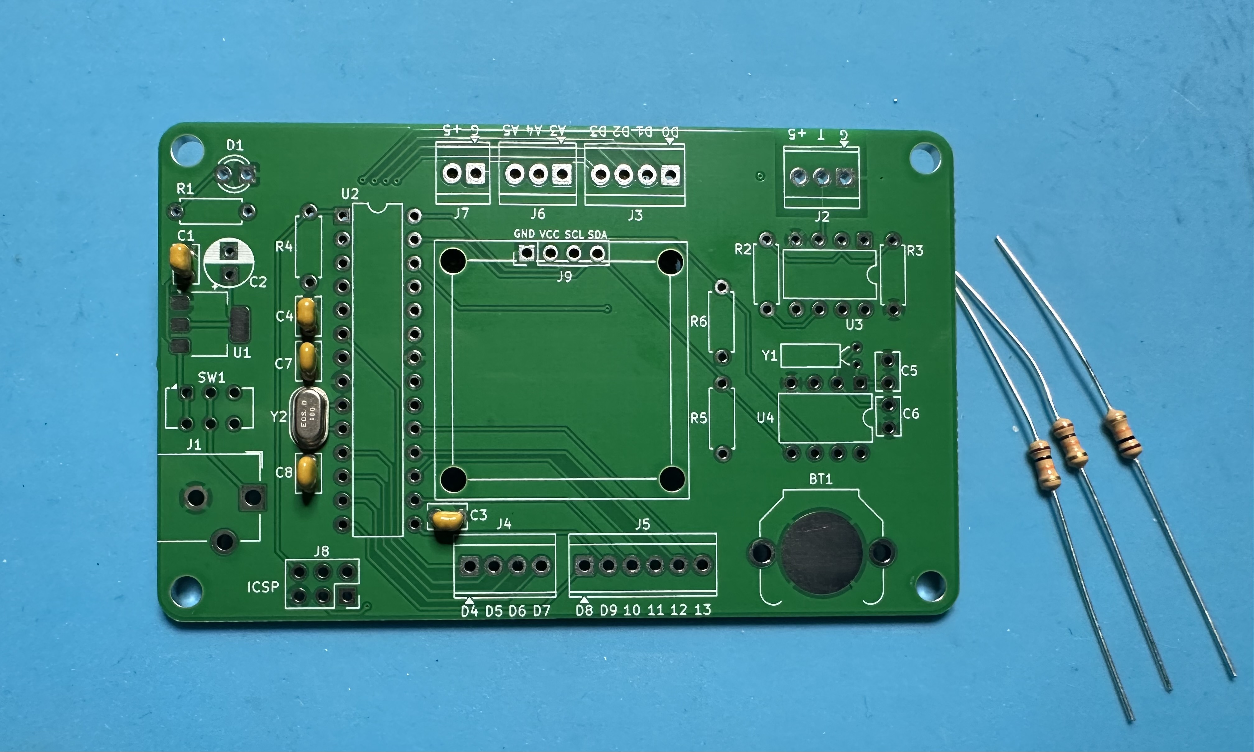
- Three 10-kΩ resistors (brown-black-orange) resistors. These are 5% tolerance resistors. Two are pullups for the I2C serial communications channel (R2 and R3) and one is the pullup for the Atmega reset (R1).
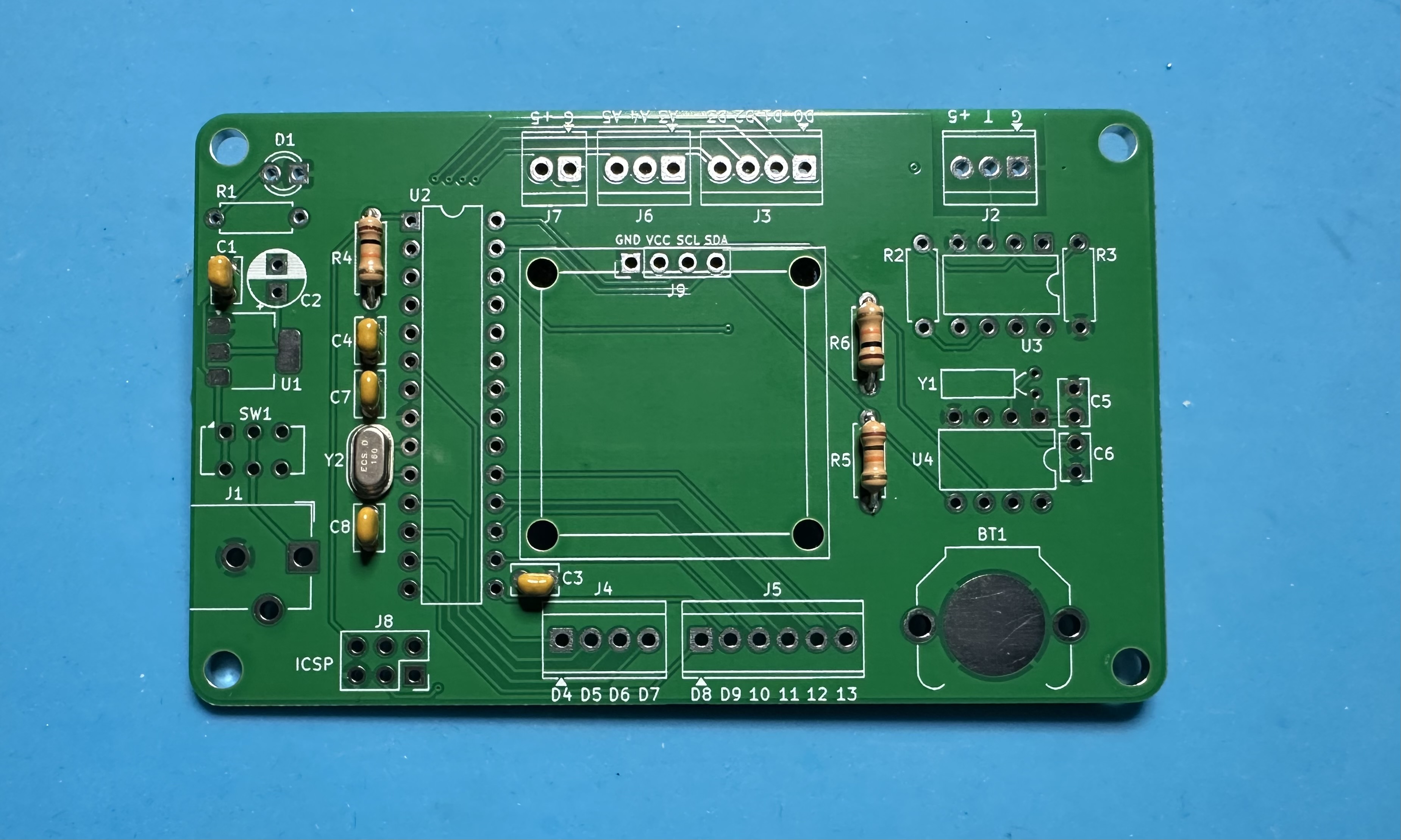
- Two resistors for the amplifier feed-back network. These are 1% resistors for better gain accuracy and are colored blue (versus the tan bodies of the 5% resistors.) The 10-kΩ resistor (brown-black-red-black) resistor is R4, and the 2.2-kΩ resistor (orange-orange-brown-black) resistor is R5. Don't mix them up or the amplifier gain will be wrong.

- The 32.768-kHz oscillator crystal for the real-time clock (Y2). Use care — the leads are small and bit fragile.
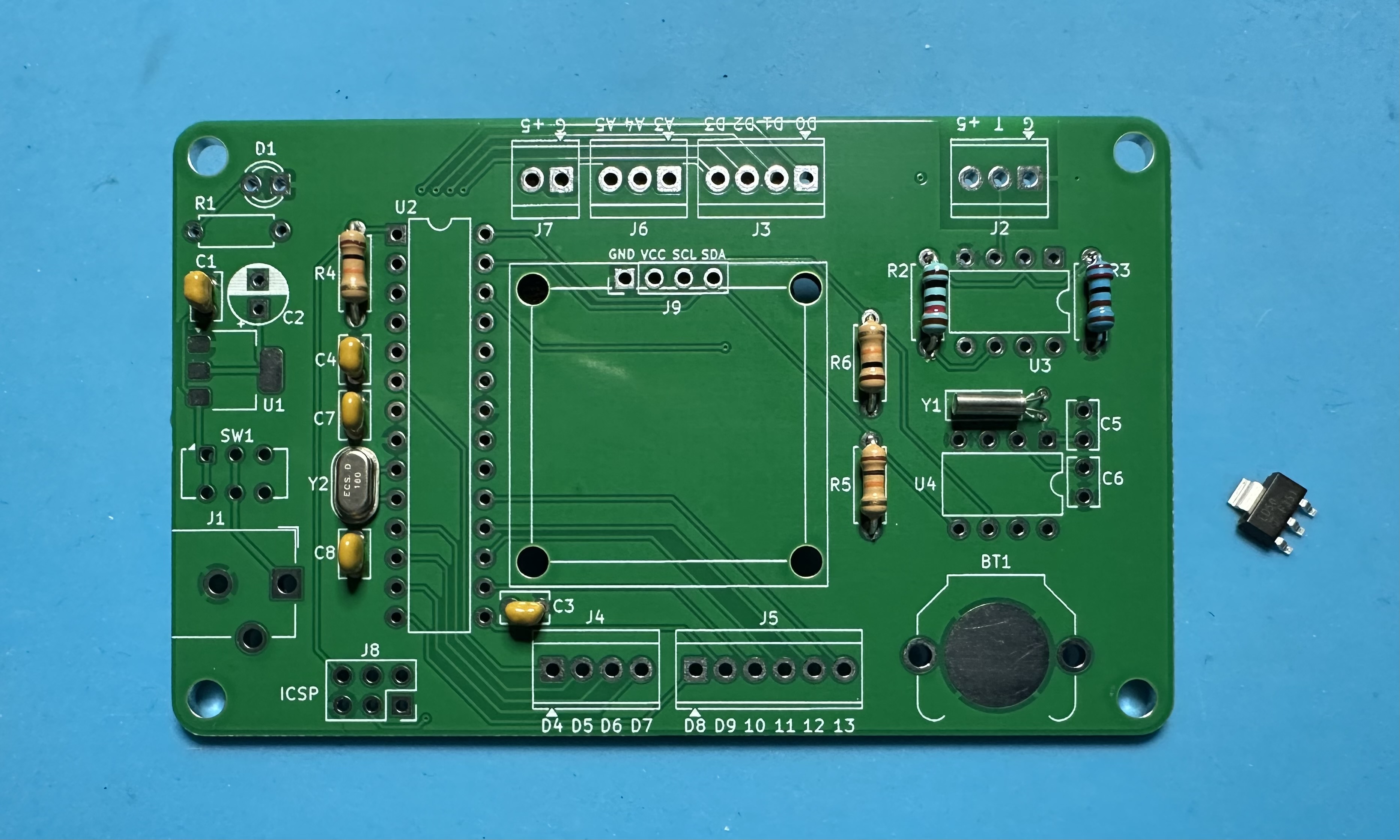
- The LD1117 voltage regulator chip (U1).
Suggested approach for soldering the surface-mount chip: First melt some solder onto one of the pads in the footprint. (It doesn't matter which pad.) Then carefully align the chip leads with the pads and hold the chip in place. (Using pliers or tweezers to hold the chip is helpful.) Use the soldering iron to remelt the solder on the one pad so that it reflows around the lead. Remove the iron and let the solder cool. Check the alignment of the leads to the pads. If the chip has slipped and the pads are not aligned, remelt the solder and adjust the chip to attain better alignment. Repeat as necessary. Once everything is aligned, solder the remaining leads to the pads.
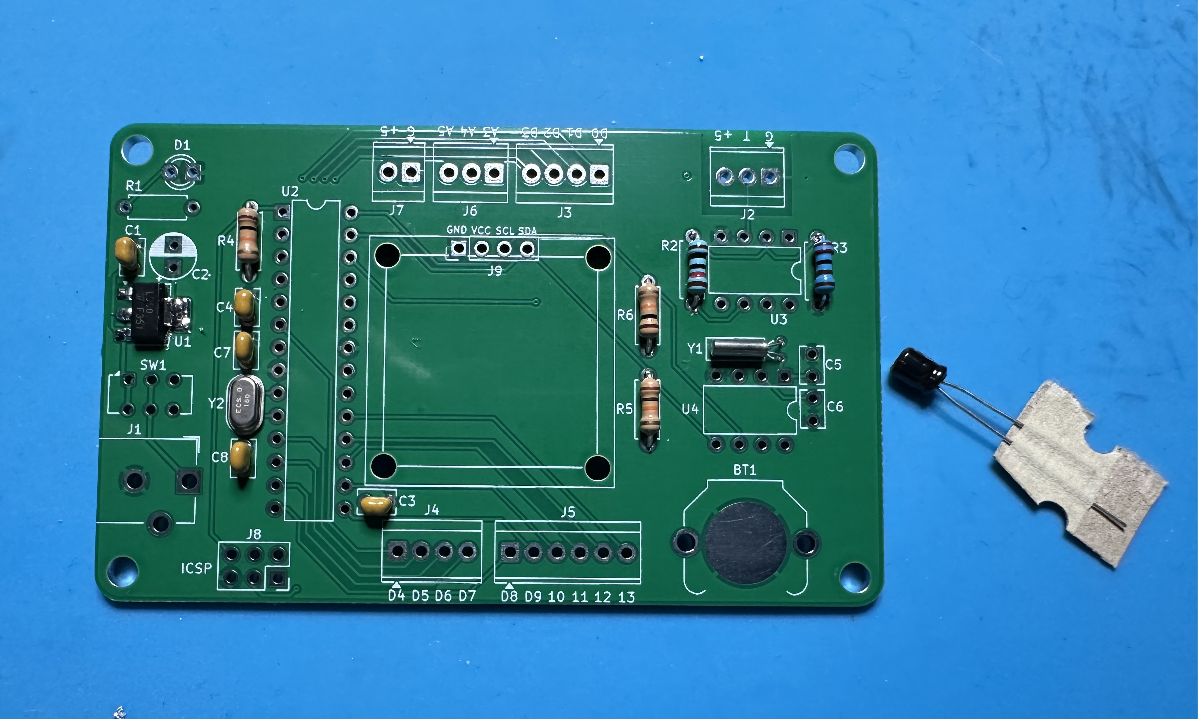
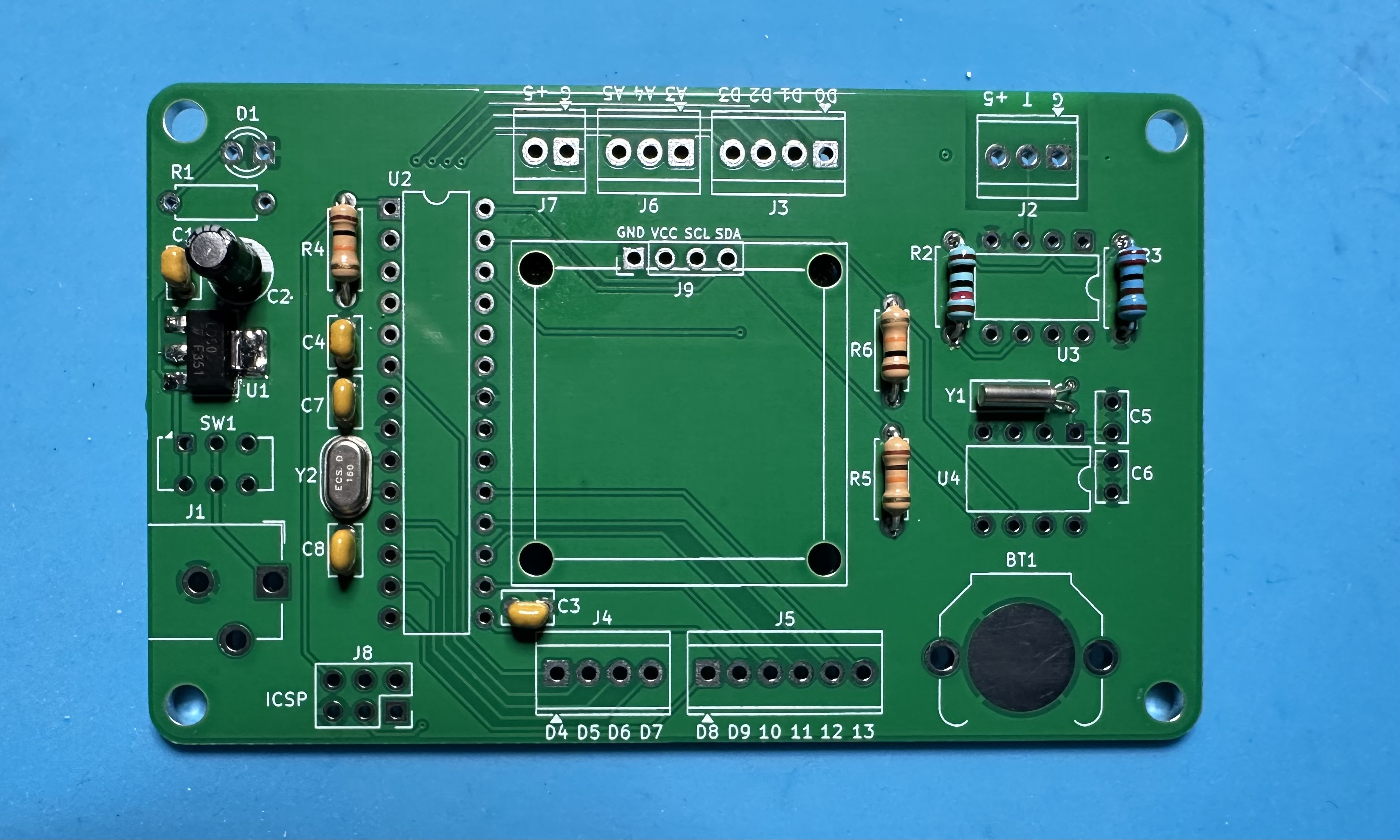
- The 10-μF capacitor for the voltage regulator. This is a polarized capacitor — make sure that the negative terminal is soldered to the white half of the footprint.
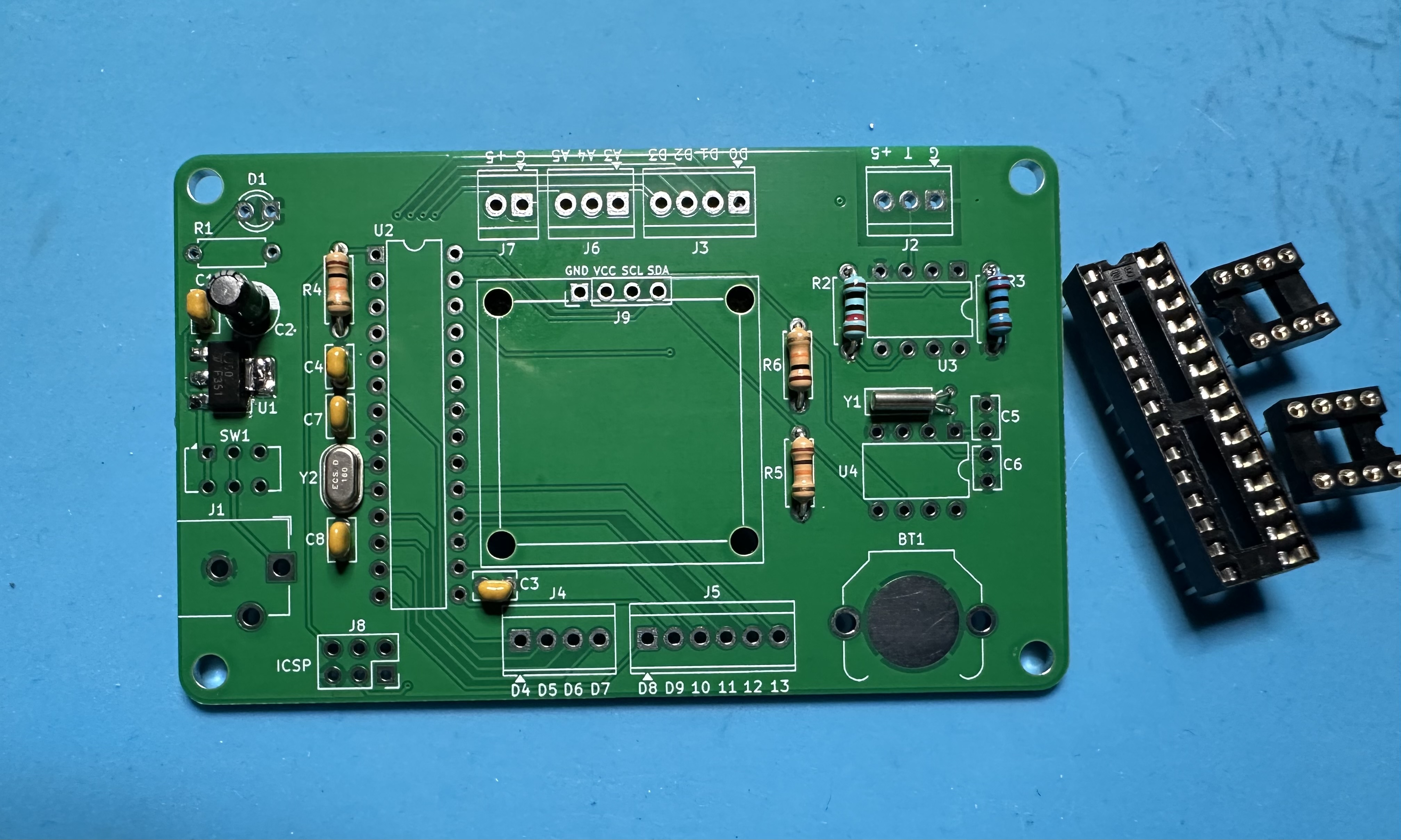
- Three chip sockets — U2 for the Atmega chip, U4 for the op amp and U5 for the real-time clock. Align the notches with the footprints, if you want, although it really doesn't matter. (If you are wondering, there is no U3 on the board. Shrug emoji.)
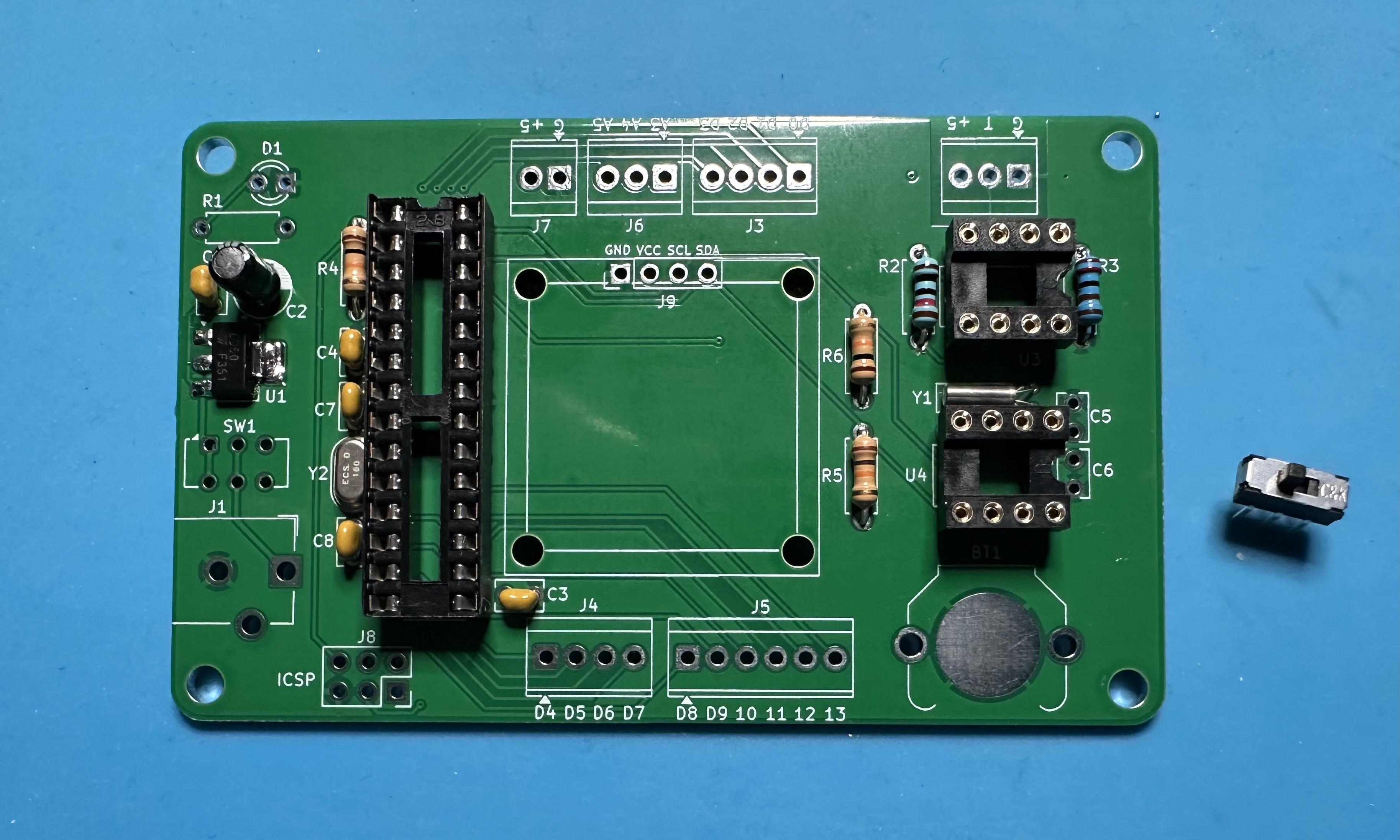
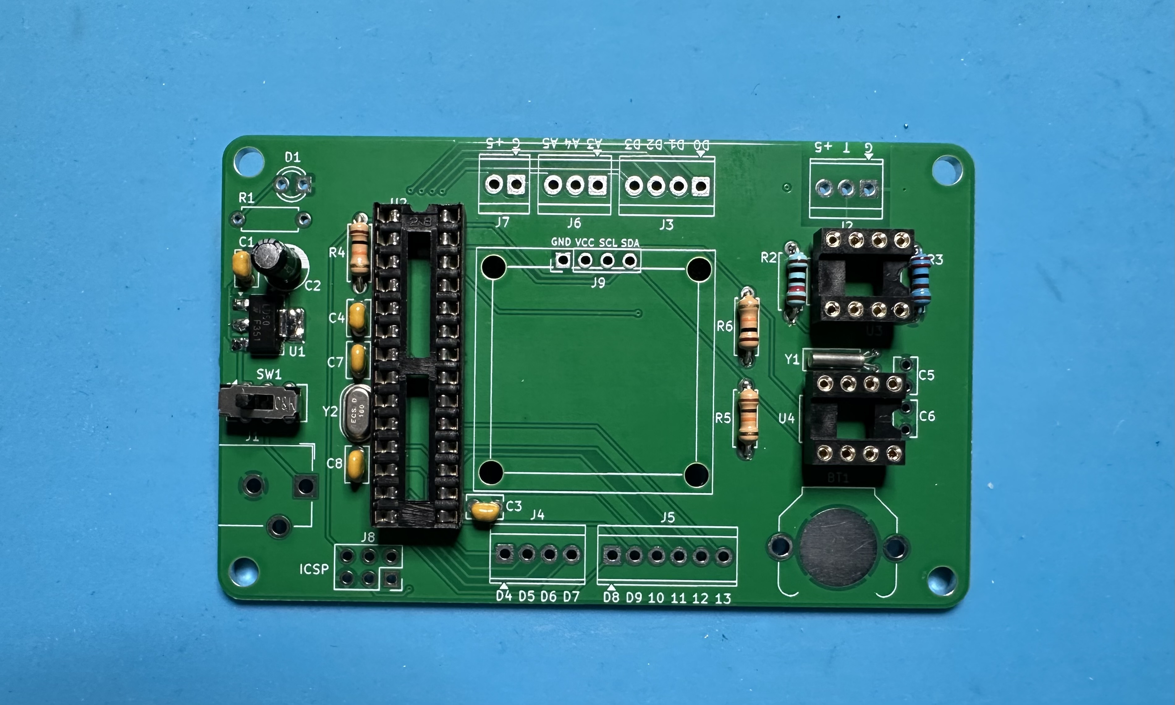
- The on-off switch (SW1). Orientation doesn't matter — it will work either way.
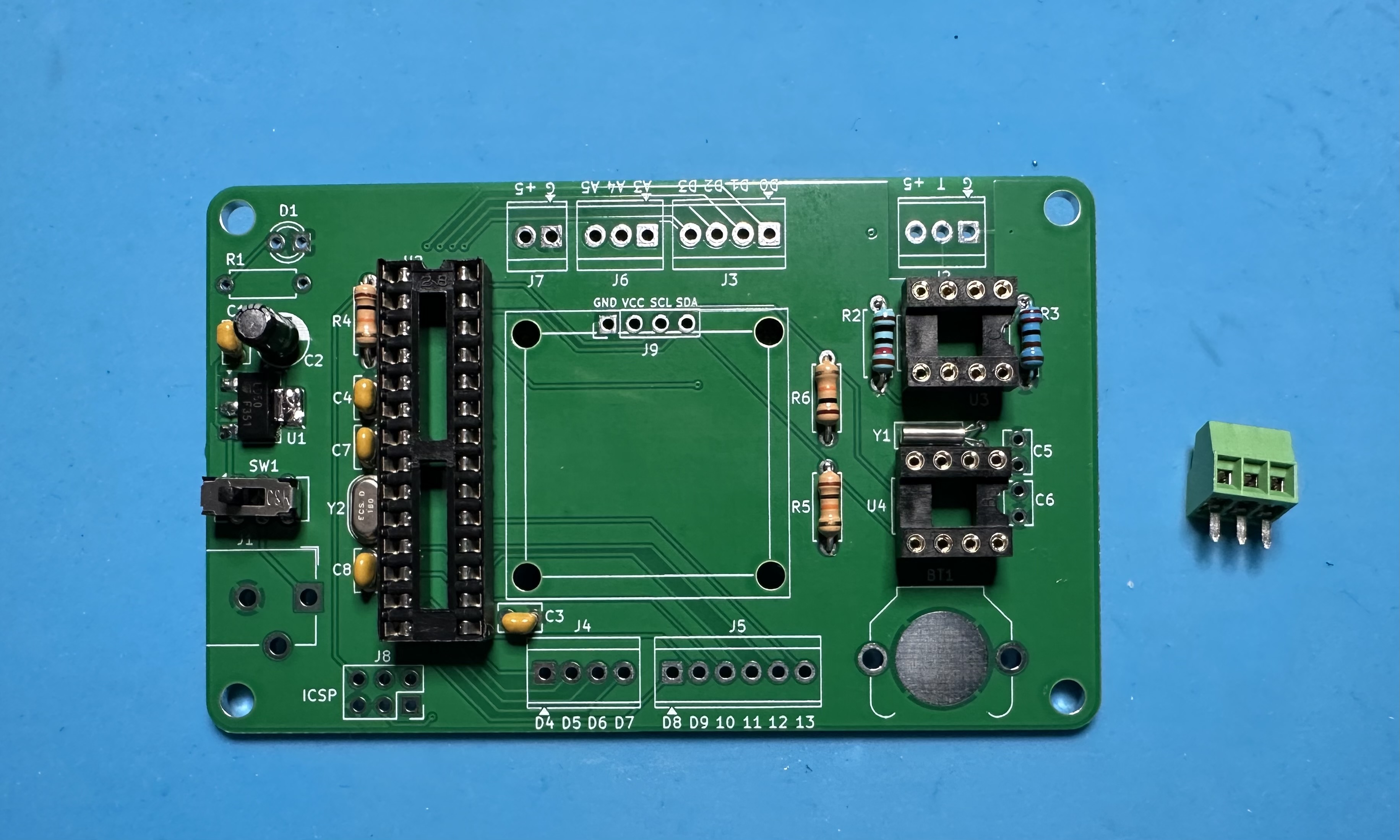
- The three-position terminal block (J3) that holds the temperature sensor. Alternatively, you could solder the sensor directly to the board, but there would less thermal isolation form the electronics and switching sensors would be much more difficult.
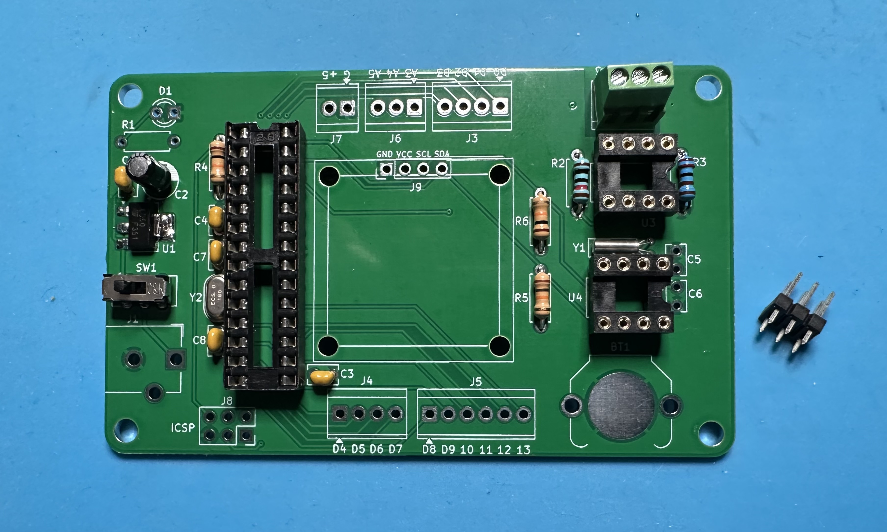
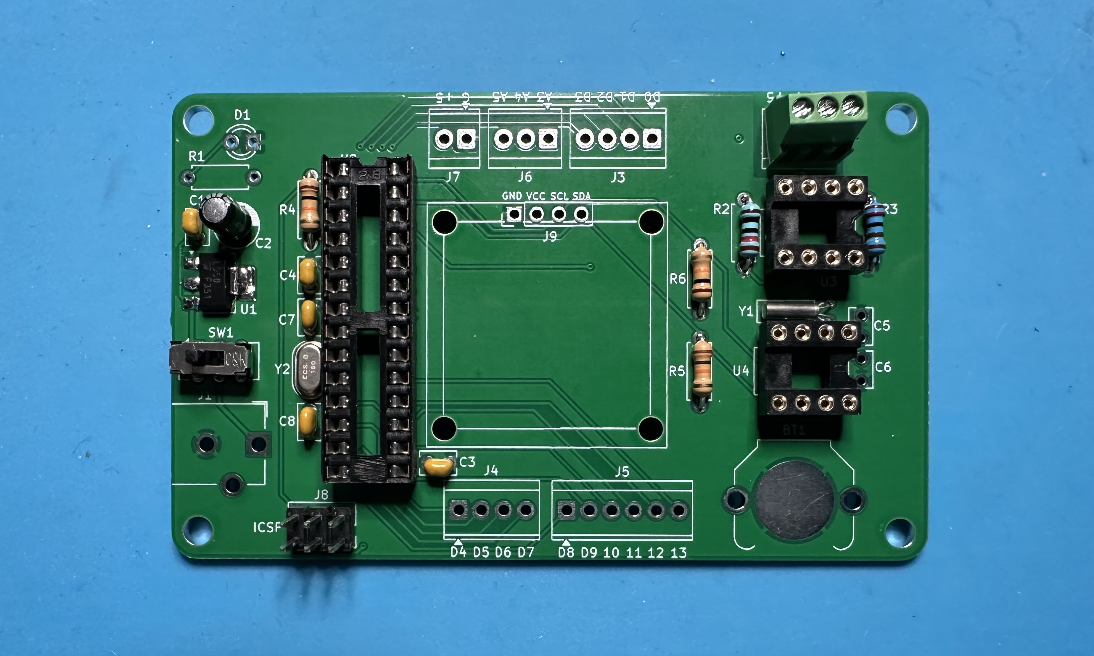
- The six-pin ICSP header for Atmega programming.
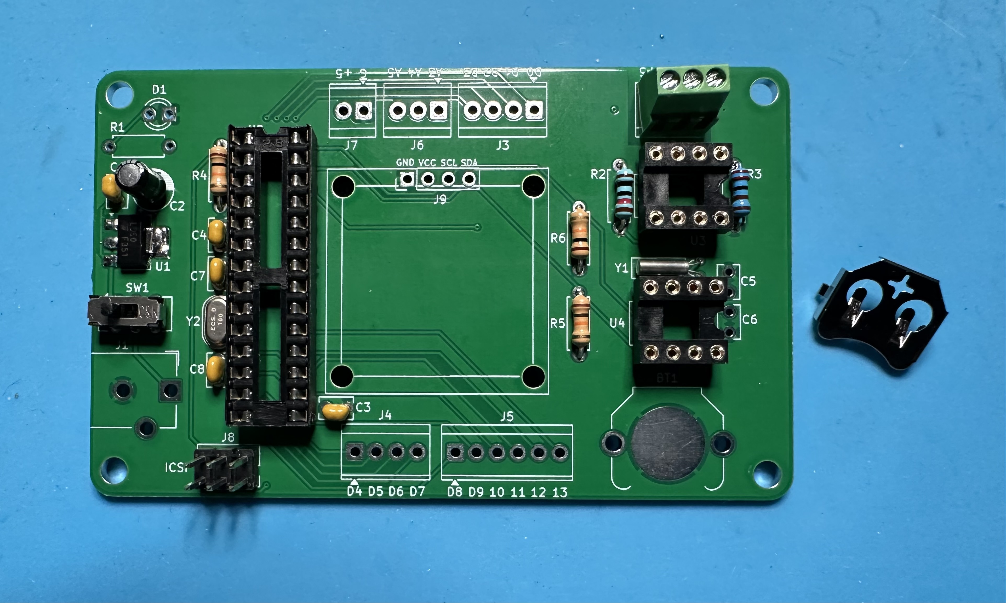
- The holder (BT1) for the CR1220 backup for the real-time clock.
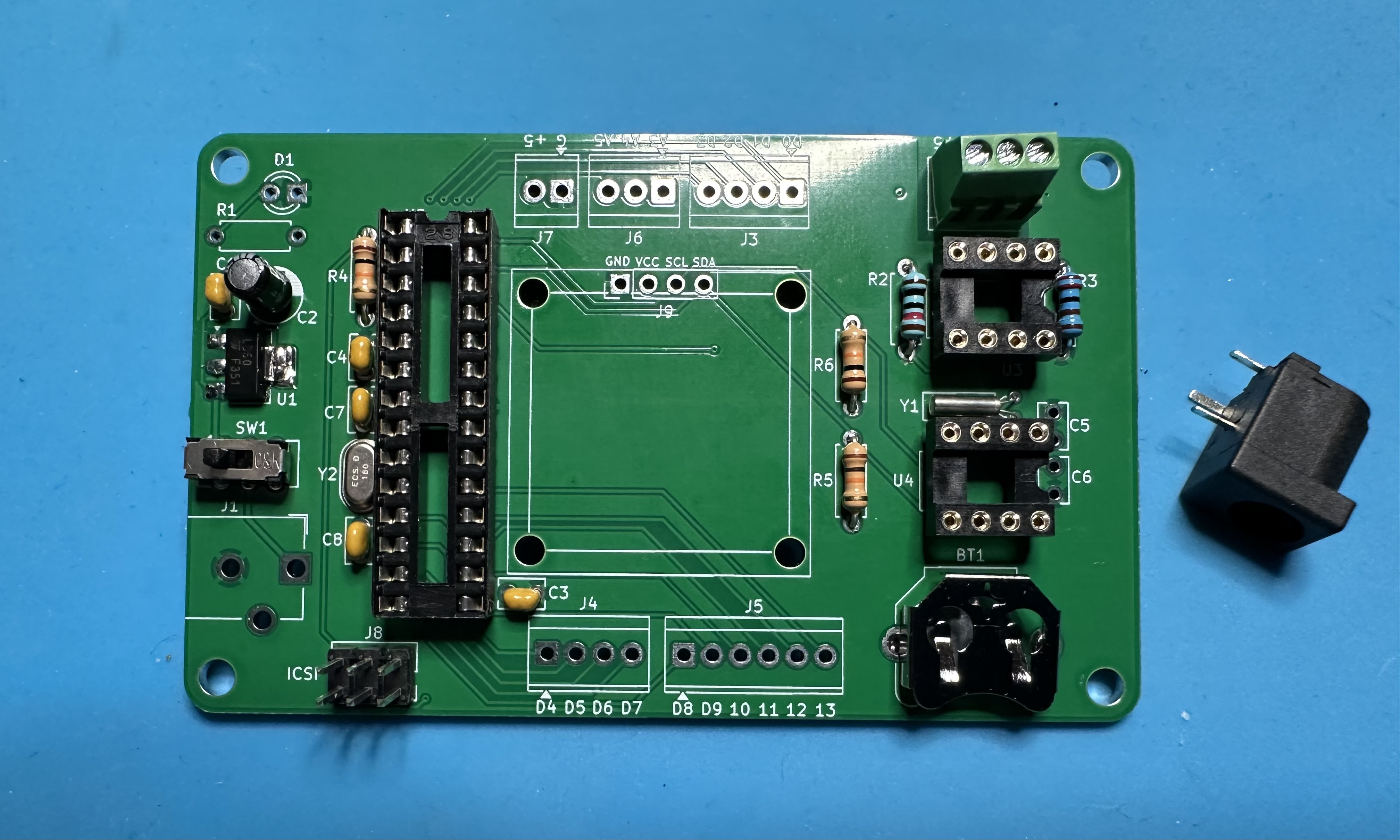
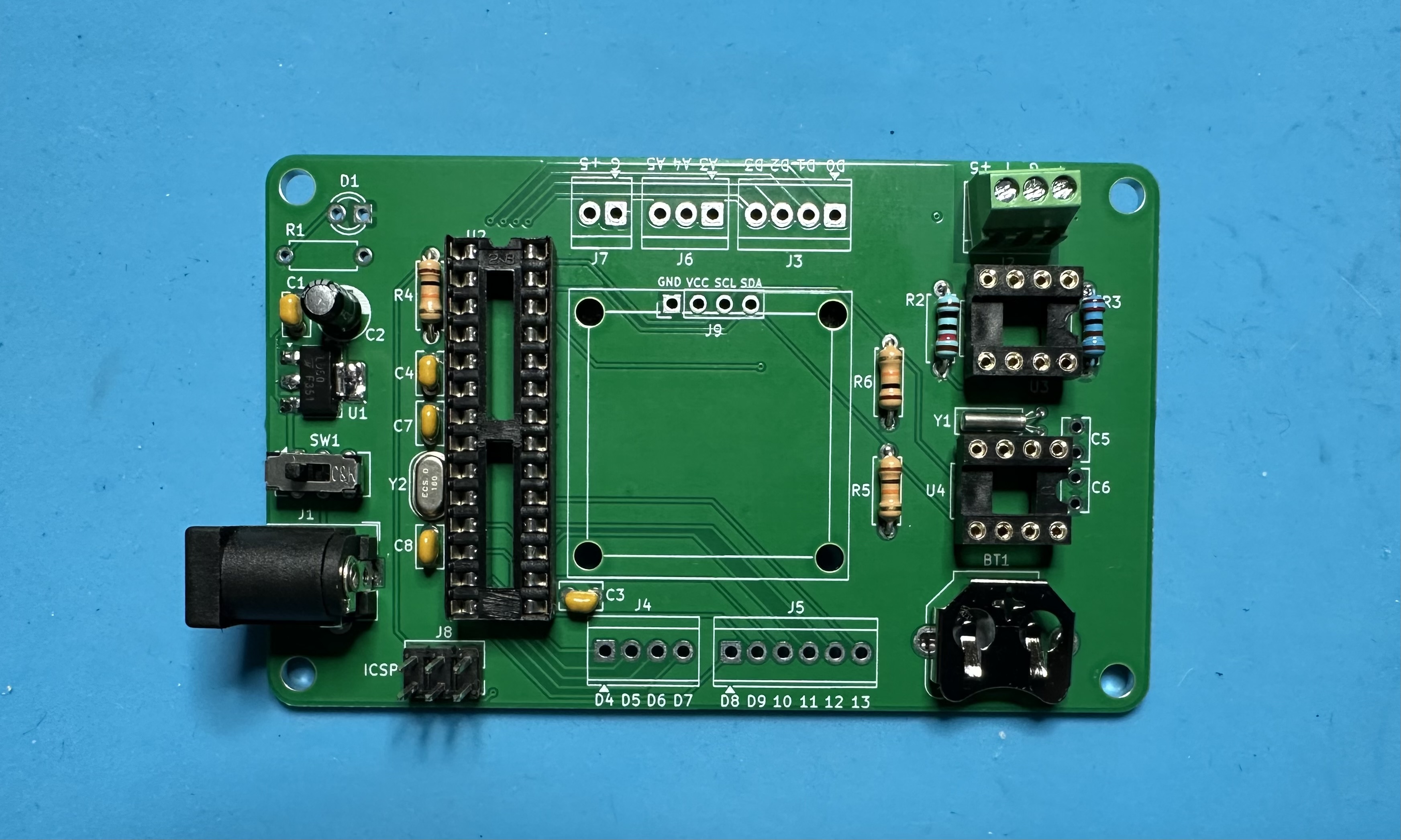
- The barrel jack (J1) for power input.
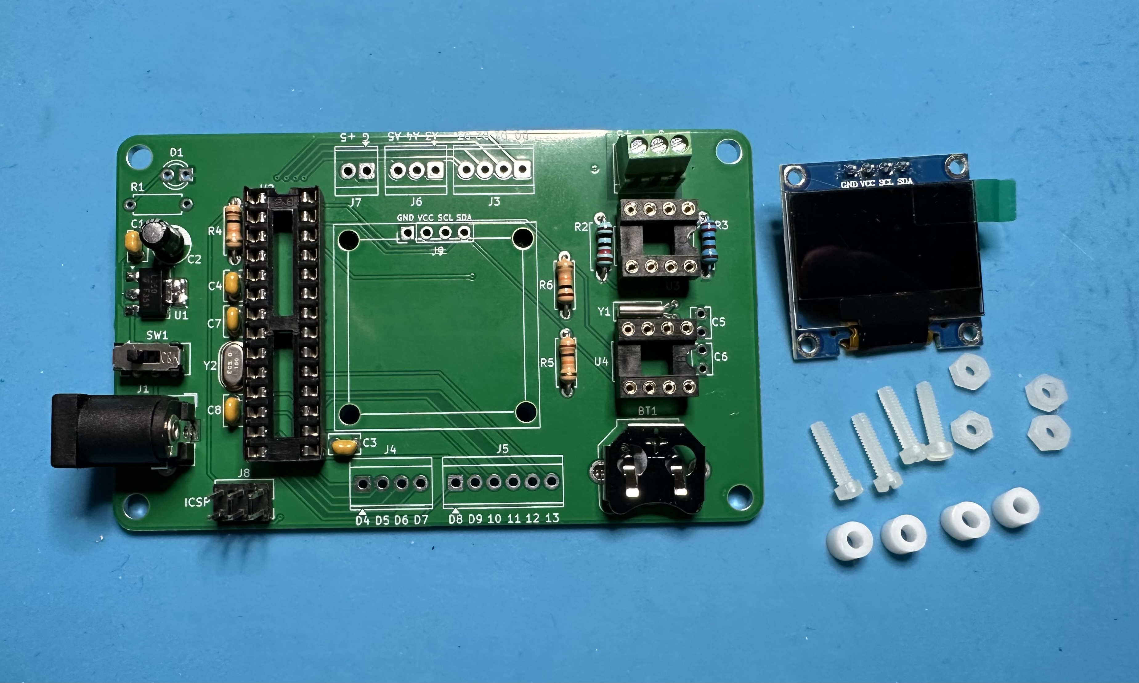
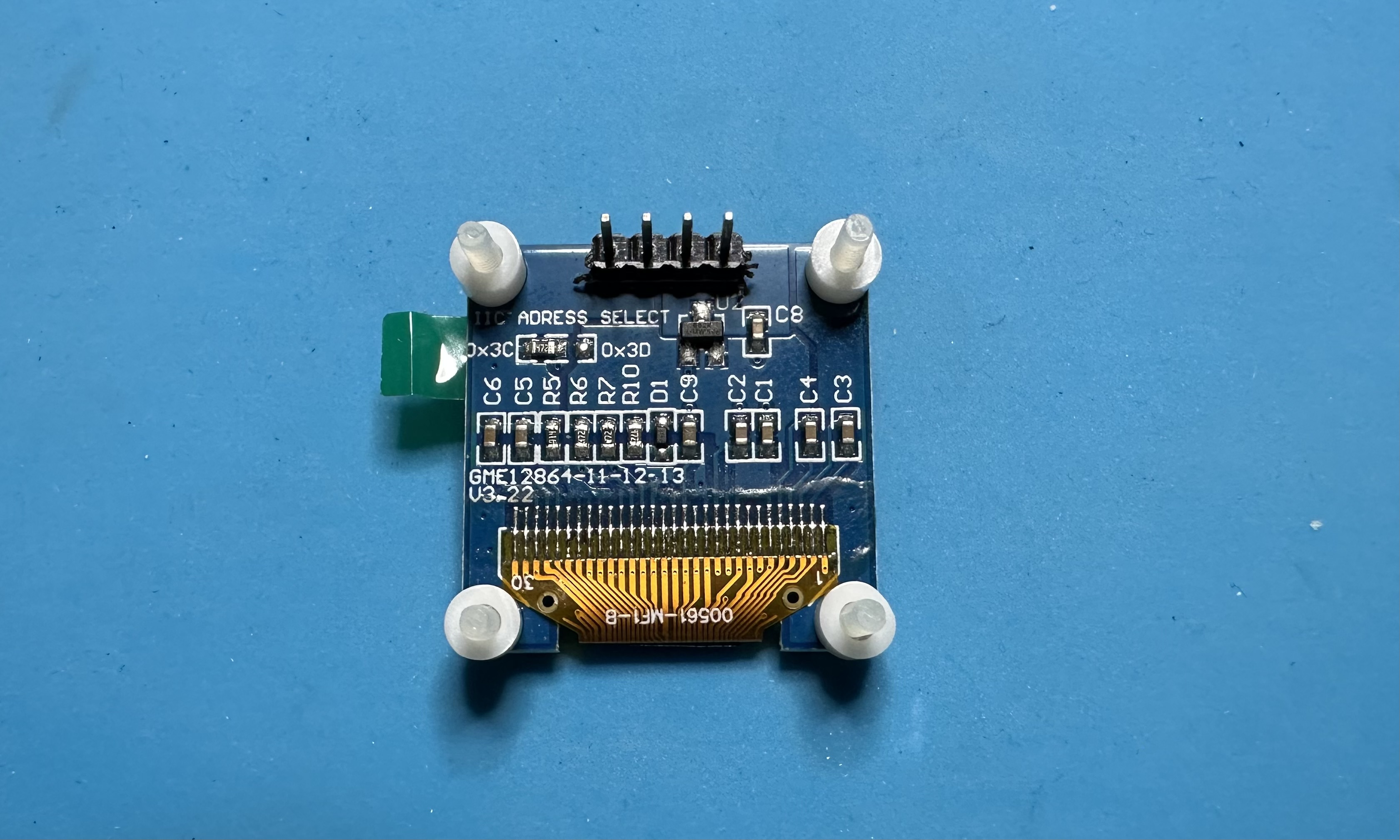
- We are ready to attach the OLED display and solder it in place. Suggested approach:
- Push the four of the nylon screws through the holes of the OLED board. It's a tight fit and you will need to apply a bit of force to get the screws through — the threads should be fine.
- Turn the display over and put the four spacers on the screws.
- Turn the PCB over and guide the four holes over the screws. This may require a bit of jiggering in order to align the screws and the OLED pins simultaneously. Secure the OLED to the board by threading four nuts onto the screws — use a screw driver to tighten everything up.
- Finally, solder in the four pins for the display.
- The last bit of soldering is optional. If you want a LED power-on indicator, add the LED and the current-limiting resistor.
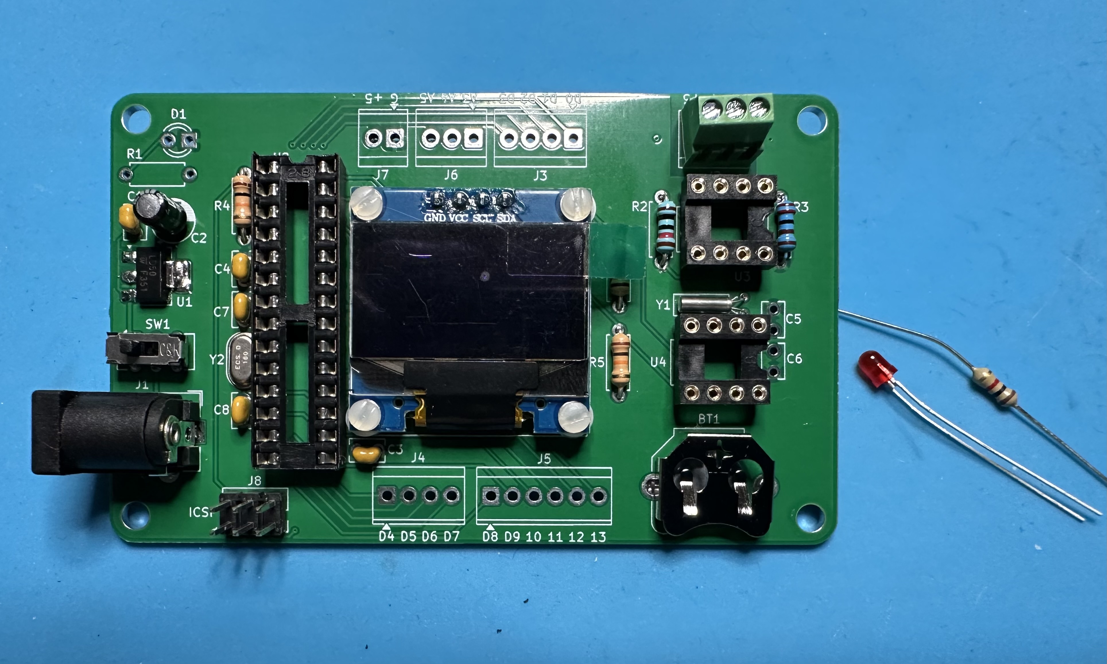
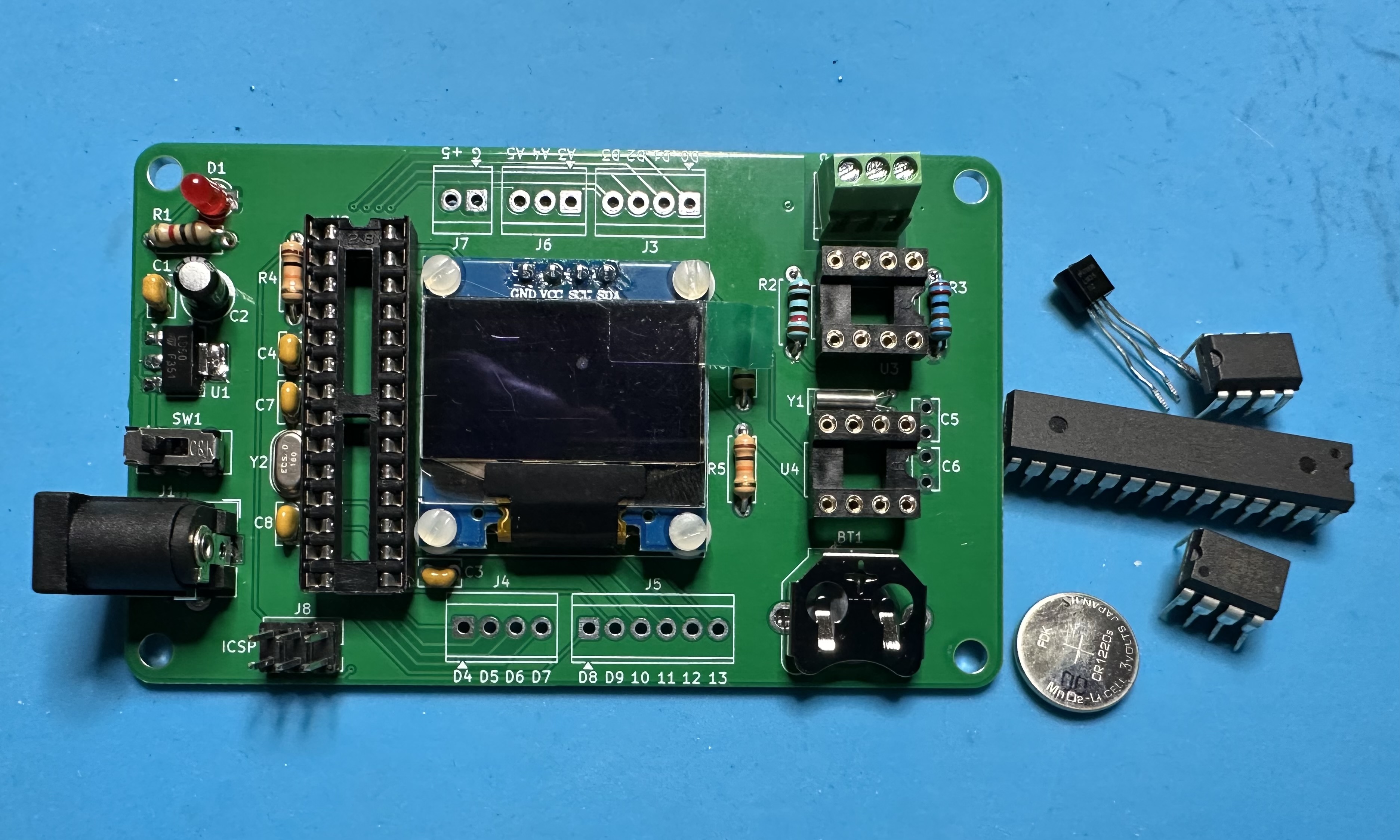
- To finish up: screw the LM35 sensor into the terminal block — flat side facing up. Insert the three chips — get the correct orientation (match the chip notch to the board footprint) and don't mix up the op-amp and RTC chips. Hold off on the CR1220 battery until the Atemga has been programmed and the clock is running.