Arduino Club
Programming the Atmega directly using ICSP
The Arduino environment is great for prototyping embedded applications. A big part of Arduino's utility is the ease of sending programs to the Atmega using the a Arduino Integrated Development Environment (IDE) running on your laptop or desktop computer. Type up your codes, hit the "upload" button, and watch the code being executed on the Arduino.
Things are less straightforward once we are ready to make our own Atmega-based hardware projects. How do we load a program onto an Atmega that is not on the Arduino? One approach is to take the Atmega chip from the Arduino and plug it into our new hardware. To do this, we would first upload the program to the Atmega using the Arduino IDE. Then we would (very carefully!) remove the Atmega chip board and plug it into a socket on the new hardware board. When power is applied to the new board, the Atmega chip should boot up and begin running the loaded program. (Assuming that the hardware was designed correctly, of course.)
There are some obvious problems with the above "program-and-swap" method. Most obviously, we would be left with an Arduino board that no longer had its Atmega chip — definitely not useful. And what if we would like make multiple copies of our new hardware gadget? In principle, this should be easy. Just buy more Atmega chips — DigiKey usually has a lot in stock. Then plug each one into the Arduino socket and program away. However, there is a big catch with this approach, as we will discuss in the next section. Another situation: What happens if we aren't using a socket in the new hardware? We might choose to solder the Atmega chip directly for cost or space reasons. In that case, we could program the Atmega in the Arduino before soldering. But this is a "one and done" approach. We would not be able to alter the program later, at least not without going through the tedious process of unsoldering the 28-pin chip.
Ultimately, we need a way to program Atmega chips directly. Fortunately, there are several approaches that will work. But first, we need to discuss the...
Bootloader
Computers have standardized on USB as means for communicating with peripheral devices. However, Atmega328 chips are not able to communicate directly via USB — there is no built-in USB interface. Arduino mitigates this problem by providing an intermediary in the form of a second MPU chip on the Uno R3 Arduino board. (The other chip is the small, square surface-mount part near the USB connector.) This second MPU — a Mega16U2 chip — has one job: to convert the serial data stream from the USB port a serial data stream that works for the Atmega328 chip. And vice-versa. The interface MPU is what makes programming the Arduino trivial.
In ordert to communicate with the interfacing chip, the Atmega328 needs keep a small bit of code in memory. This sliver of code is called the "bootloader". Without it, the Atmega328 cannot communicate with the interfacing chip and so cannot communicate with the computer. The Atmega328 is useless.
Here is the problem: new, fresh Atmega328 chips do not come with an Arduino bootloader installed. (Not all Atmega328s are meant to be installed in Arduino boards.) So we have a classic Catch-22 conundrum: In order to install the bootloader, we would first need to have the bootloader installed. Stated another way, an Arduino cannot install its own bootloader.
The previous sentence suggests a way around the conundrum: we can use a functioning Arduino to "burn" a bootloader onto a separate Atmega328 chip. There are several ways to set up an Arduino to serve as the "programmer" for writing programs to other chips, to be described below.
SPI
Interfacing two Atmega328s, one in an Arduino and one that will be programmed, involves using a serial peripheral interface (SPI). SPIs are common in the embedded systems and are used to connect a variety of peripheral devices to a microcontroller. Examples of peripheral include certain types of sensors, digital potentiometers, external ADCs and DACs, SD cards, displays, and input devices. In our case, the Arduino will be the controller and the un-programmed ATmega328 chip will be the peripheral.
A generic SPI has four connections.
- One connection is for serial data streaming from the controller to the peripheral — controller out, peripheral in (COPI).
- A second connection is for data to flow the other way — controller in, peripheral out (CIPO).
- The third connection is for a serial clock (SCK) signal the synchronizes the flow of data.
- The fourth connection is a chip select (CS) the specifies a particular chip if there are multiple peripherals communicating with controller.
For the specific case of using SPI to program a peripheral chip using a controller, we use a slightly different acronym...
ICSP
An in-circuit serial programming (ICSP) interfaces refers specifically to programming chips. The ICSP has three of the usual SPI connections — COPI, CIPO, and SCK. (Ugh. So many acronyms.) Since the controller will program only one chip at at time, the chip-select connection is repurposed to become a reset (RST). Once the program has been transmitted to the peripheral chip, the controller will hit the reset on the peripheral to start up the program. Thus on the CS on the controller must be connected to the reset on the peripheral.
Also, even though the peripheral does not initially have a program, it must be operating as an MPU to receive the program. So it needs to powered up with 5-V and ground connections. The ICSP includes power (VCC) and ground (GND) connections. The controller will be providing power to the peripheral. Also, to be operational, the peripheral chips should have a functioning clock oscillator. This could be faked by sending a square wave from the controller to serve as the peripheral clock, but our approach will be to include an oscillator crystal and capacitors so that the peripheral can run on its own.
So the ICSP interface has six connections:
- COPI. Connect COPI on the controller to COPI on the peripheral.
- CIPO. Connect CIPO on the controller to CIPO on the peripheral.
- SCK. Connect SCK on the controller to SCK on the peripheral.
- RST. Connect chip select (CS) on the controller to the reset pin of the peripheral.
- VDD. Connect VCC on the controller to VCC on the peripheral.
- GND. Connect ground on the controller to ground on the peripheral.
On the Atmega328 chip, certain digital pins are defined for use with SPI, and Arduino has its own way of denoting pins. So when making the ICSP connections to program a chip, we need to be sure to make the correct connections between the Arduino working as controller and the Atmega328 chip as peripheral. The connections mapping is given in the table below.
| ICSP name |
ICSP function |
Arduino digital pin |
Atmega328 pin |
| RST |
Chip Select / Reset |
10 |
1 |
| COPI |
Controller Out, Peripheral In |
11 |
17 |
| CIPO |
Controler iOut, Peripheral In |
12 |
18 |
| SCK |
Serial Clock |
13 |
19 |
| VCC |
Positive voltage supply |
5 V |
7 |
| GND |
Ground |
GND |
8 or 21 |
"out of circuit" programming – using a breadboard
If the embedded system we are developing uses a socket to hold the Atmega328 chip, it is easy to program the chip first, "out of circuit", before plugging it into the socket. The are four basic steps.
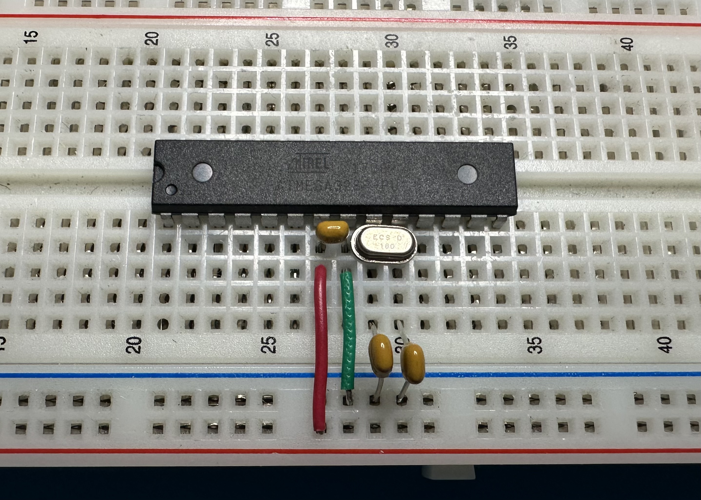
- Set up the peripheral Atmega in a bare bones configuration on a breadboard.
- Plug the un-programmed Atmega into the breadboard.
- Make a connection for ground, pin 8. (Green wire in the photo.) If you like to play it safe, you could also connect pin 21 to ground, but it is probably not necessary.
- Make a connection for power, pin 7. (Red wire in photo.)
- Connect a 16-MHz crystal between pins 9 and 10.
- Connect two 22-pF capacitors between pin 9 and ground and between pin 10 and ground.
- Connect a 100-nF capacitor between pins 7 and 8 to serve as a power-supply bypass. This is probably not necessary, but it doesn't hurt. (Some online instructions claim that the bypass is absolutely essential in order for the programming to work. My experience has been that the bypass capacitor really doesn't make any difference.)
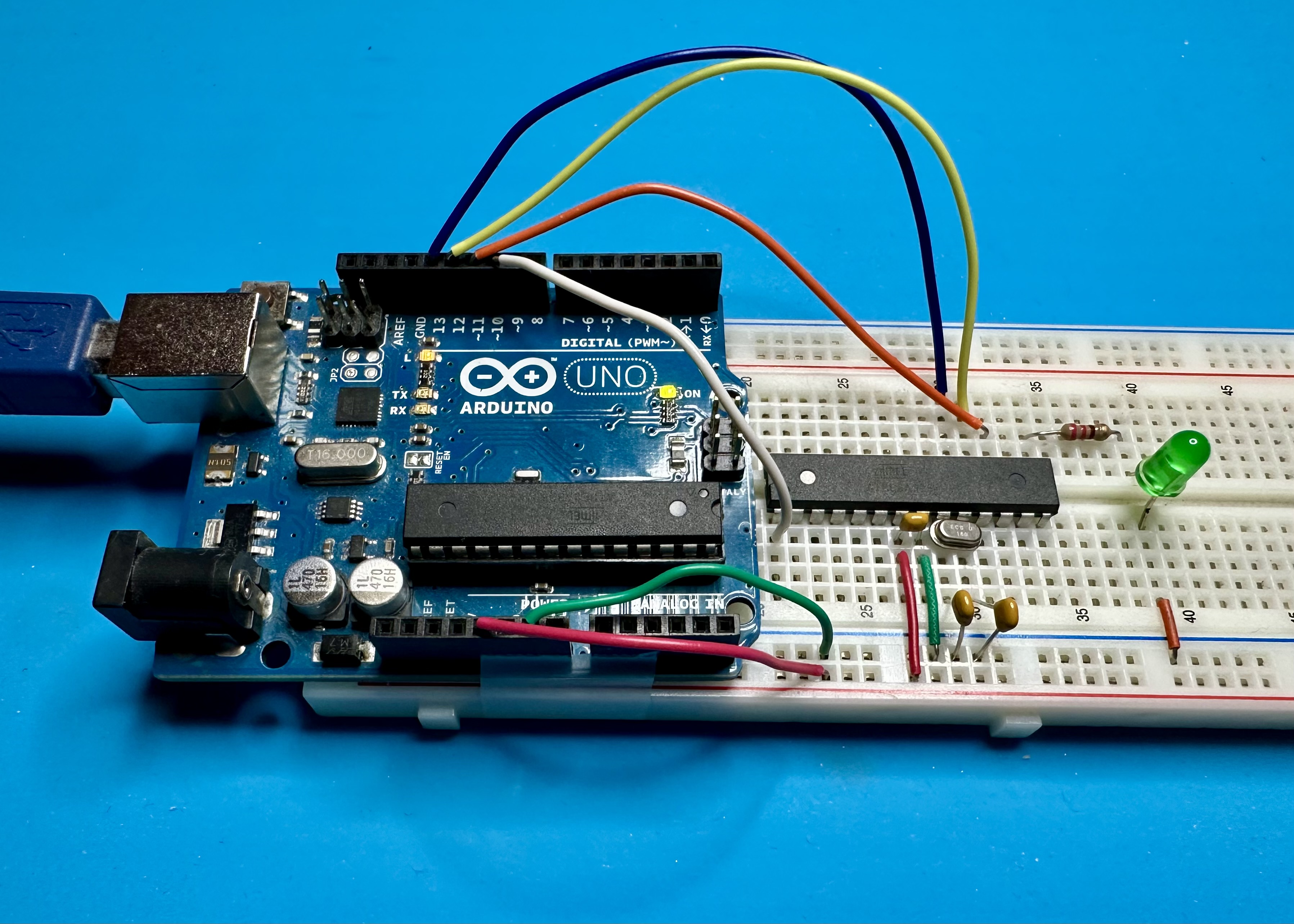
- Then make the six connections between the Arduino controller and the Atmega peripheral on the breadboard. Use the table above to guide the way.
- Next, set up the Arduino to serve as a controller. In the Arduino IDE, bring up the "ArduinoISP" sketch. (From the menu: File → Examples → 11.ArduinoISP → ArduinoISP.) Upload the AruduinoISP sketch to the Arduino. This sketch turns the Arduino in a controller that will program whatever is connected to its ICSP interface.
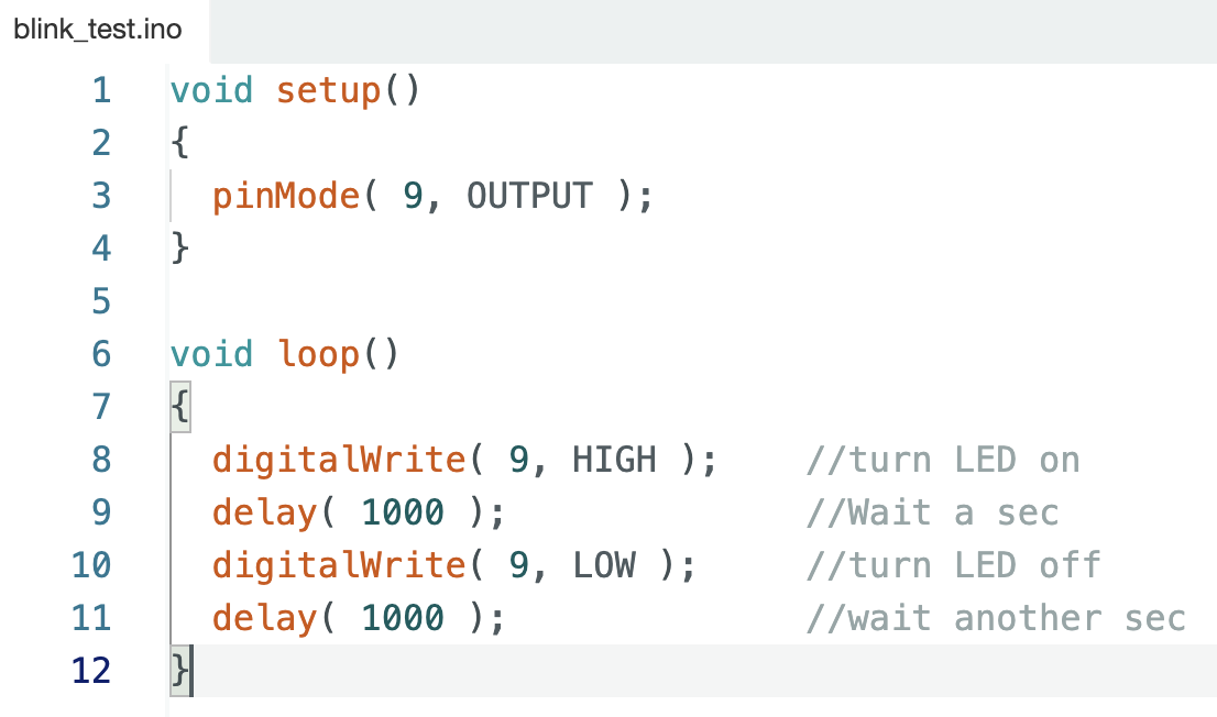
- Finally, bring up the sketch that is to be uploaded to the peripheral Atmega328. For this example, we will use a simple variation of the standard "Blink" sketch. The sketch blinks an LED connected to Arduino digital pin 9, which is physical pin 15 on the Atmega chip.
So to observe this sketch in operation, we should connect an LED to pin 15 via a 200-Ω current-limiting resistor, as shown in the photograph above.
There are two steps required to send the sketch:
- Set up the IDE to use the Arduino as a controller (or programmer in the parlance of the IDE). (From the menu: Tools → Programmer → Arduino as ISP.)
- Then, to send the program, use the menu command: Sketch → Upload Using Programmer. This sends the sketch through th Arduino controller (programemer) to the peripheral Atmega chip.
If all the wiring, IDE set up, and sketch code was done properly, the sketch should start running in the peripheral Atmega. In our example, the LED should start blinking off and on.
"out of circuit" programming – using the Arduino Club programmer shield
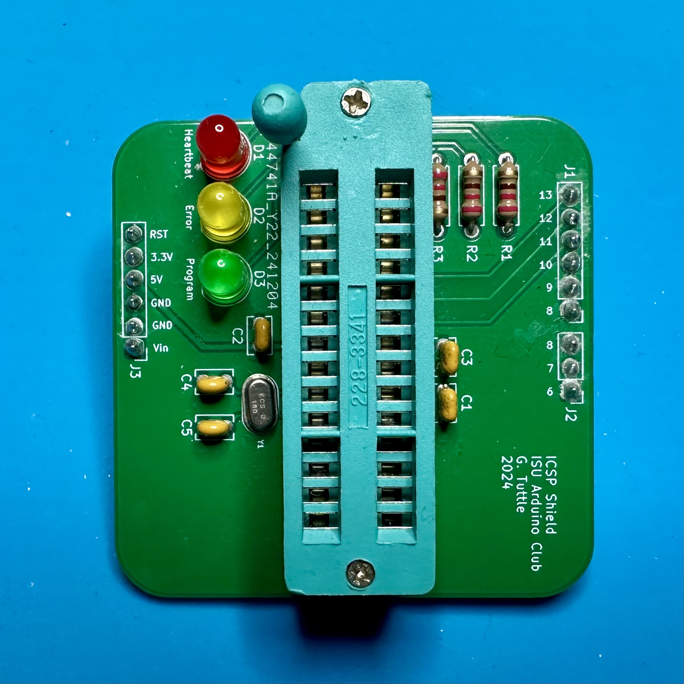
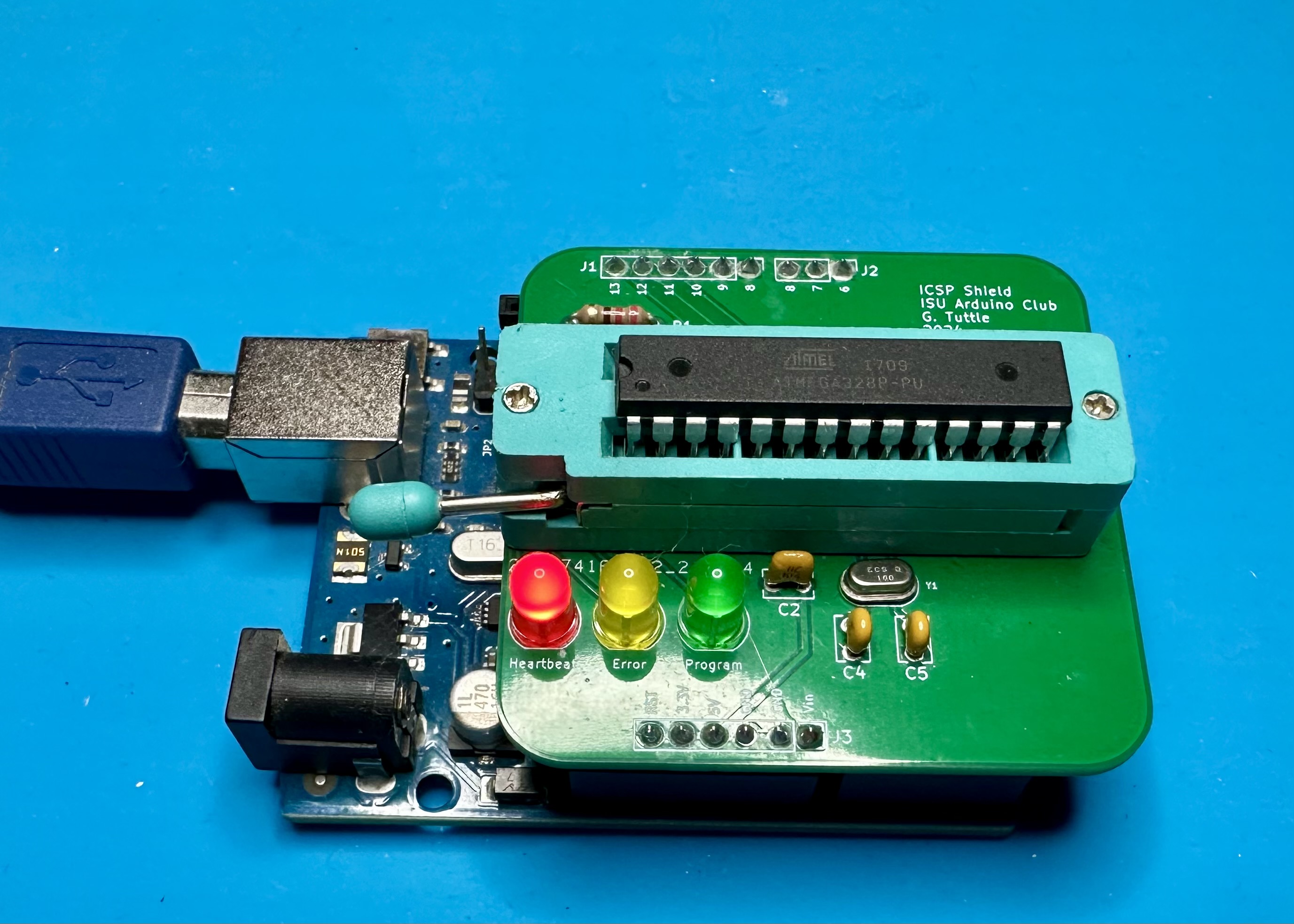
All the wiring needed to do programming using the breadboard is tedious and probably error prone. We don't have to do this exercise too many times to realize that it could all be streamlined using a PCB. The PCB would be in the form of an Arduino shield that plugs directly into the headers on the Arduino board. Then the Atmega to be programmed can be plugged into the PCB. The PCB would have the oscillator crystal, by-pass capacitors, and connections for the using the Arduino as a programmer. If we use a "zero-insertion force socket" (ZIF) for the peripheral chip, we can the fraught process of trying to plug a 28-pin into a regular socket.
To use the shield:
- Plug the shield into the Arduino headers. The shield uses only a few pins, but there are enough to make all connections and also provide some stability. Make to sure to align the pins on the shield with the headers on the Arduino.
- Plug the Atmega to be programmed into the ZIF. Move the lever open the sockets, insert the chip, and then move the lever back to clamp the sockets to the chip pins.
- Set up the Arduino to serve as a controller (programmer). Same as step 3 in the previous section.
- Send the sketch to the Atmega chip. Same as step 4 in the previous section.
- Remove the programmed Atmega chip from the ZIF and plug it into the socket of your hardware prototype.
Simple!
The shield has provision for three LEDs. These are totally optional — they could completely omitted without having any effect on the programming process. One LED is a "heartbeat", which is simply indicates that the "Arduino as ISP" sketch is running on the Arduino controller. A second LED is supposed to indicate an error condition. (In my experience, this always comes on once the sketch has finished loading. So it is unclear if it is working correctly.) The third LED flashes while the sketch is loading, basically indicating "in process".
Here are instructions for building the shield. Building it is one the easier Arduino-club projects.
Programming "out of circuit" is easy — particularly with the shield — and works well when our prototype has a socket. But there are often situations when it would be useful to...
Program "in circuit"
Usually, when writing and debugging software for an embedded an application, there will be many iterations of the code. Even with the shield, the process of unplugging the Atmega MPU from its prototype board, plugging it in the programmer, uploading the program, unplugging it from the programmer, and finally plugging back into the prototype board would quickly become very tedious. It would be much simpler to send the program to the Atmega while it is "in circuit." And if the prototype PCB did not have a socket and the Atmega chip was soldered in directly, there would no option but to program in circuit. Of course, this is entirely possible and should be easy, as long as the prototype hardware is set up properly.
The process for in-circuit programming is exactly the same as that for out-of-circuit as long as there is access to the pins used for ICSP. Then is is just a matter of connecting the controller directly to the prototype board. As an example of how it works — and what might go wrong — we can program a Cyduino directly using an Arduino as controller. (Of course, the Cyduino uses a socket for the Atmega chip, so out-of-circuit programming works, too.)
The Cyduino has spots for connections to all of the standard digital pins, so it is easy to connect SCK, COPI, and CIPO. Power and ground connections are available, too. But we run into a problem with the RST connect — there is no easy connection to the reset (pin 1) on the Cyduino. (Obvious designer error. Derp.)
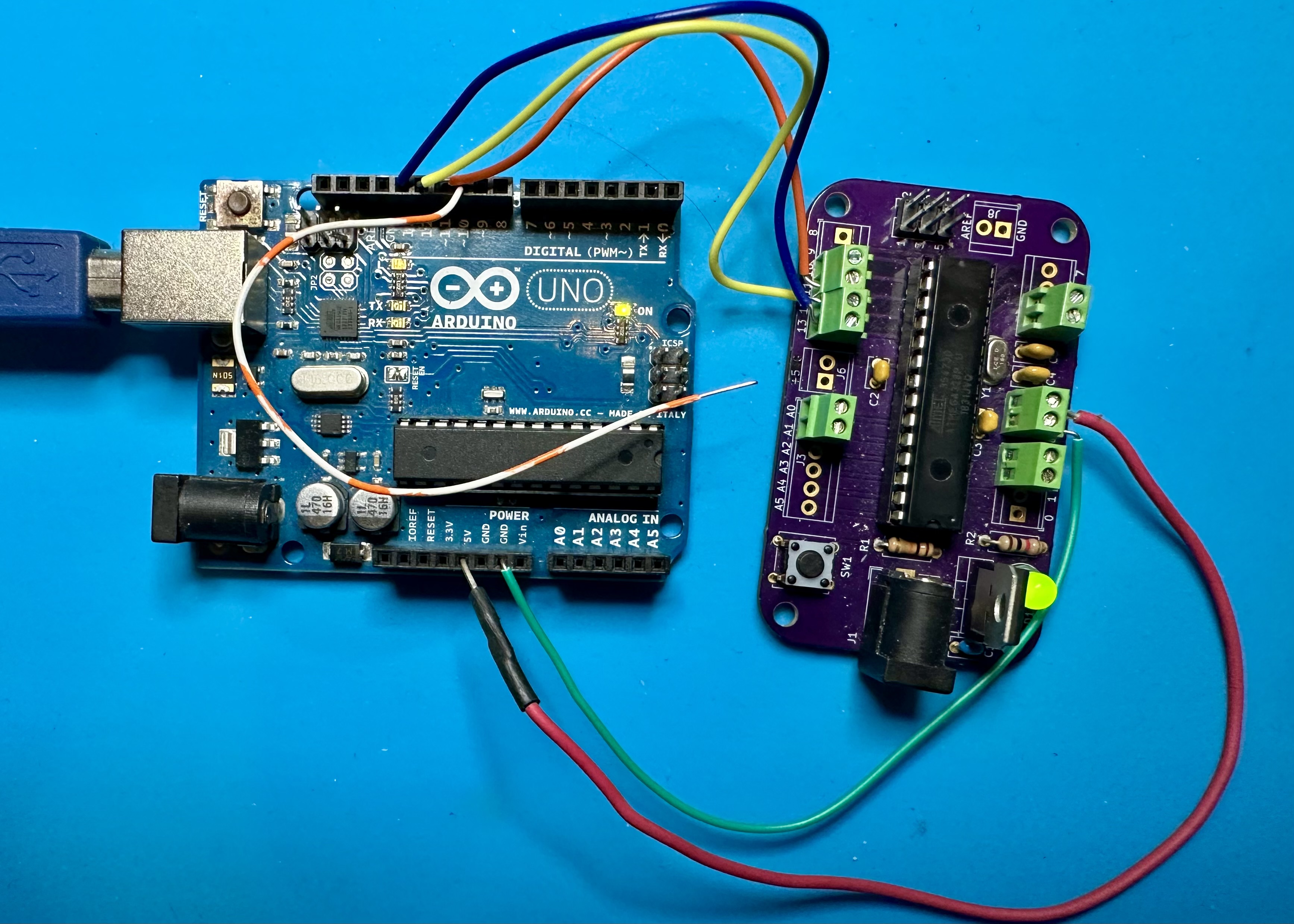
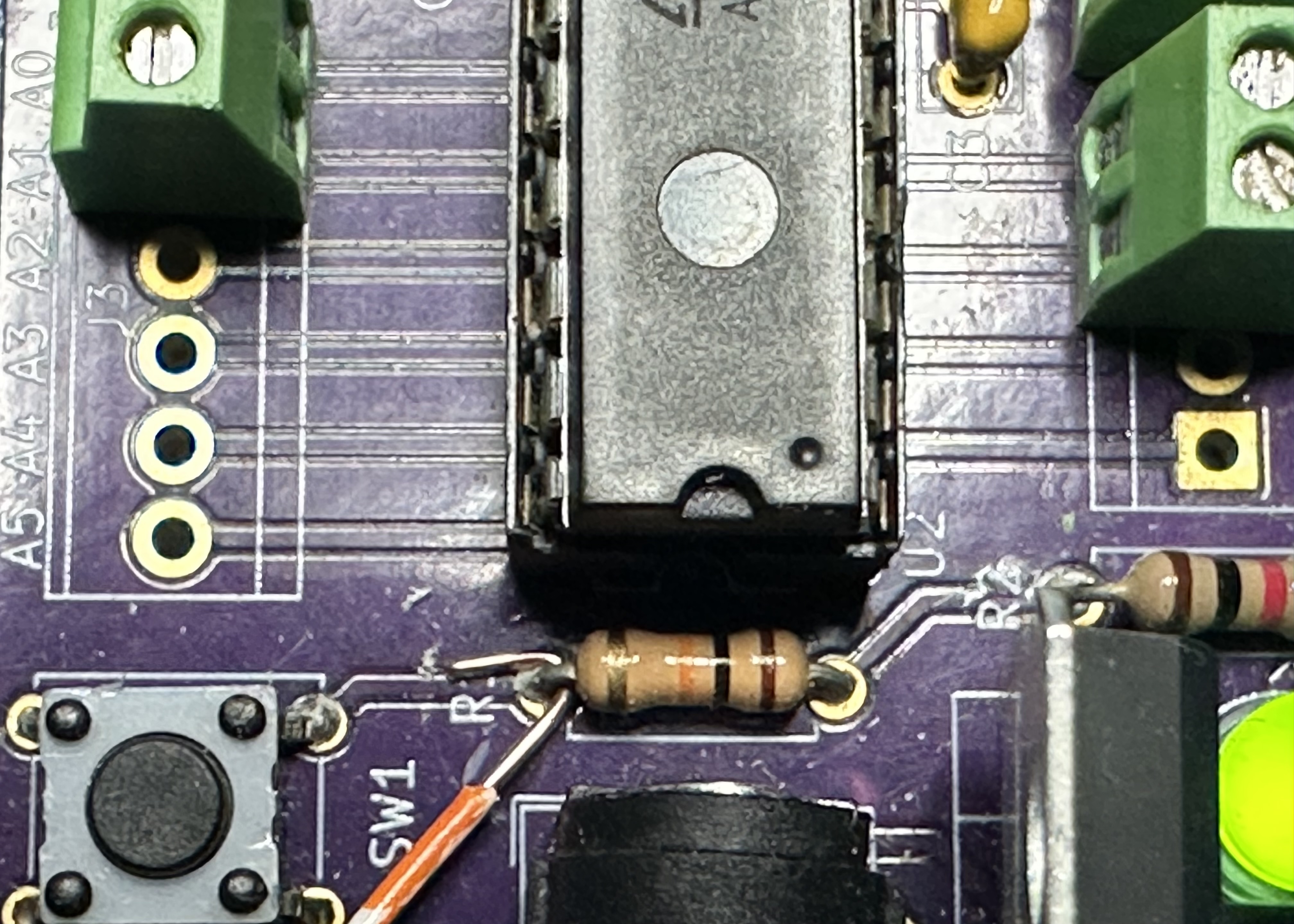
So we have find a place on the board where a wire can be squeezed in to make connection to pin 1. The reset pin connects to one end of the 10-kΩ reset resistor and to one side of the reset switch. We could just jam a wire into pin 1 on the socket, but that might be difficult since there is not a lot of space. It is probably better to try to wedge a wire under the resistor lead or the switch lead. The photo below shows the reset wire jammed under the resistor lead. Definitely janky, but it works.
But there is a better way to make in-circuit connections, and that is to use the...
ICSP Header
We have noticed these headers on the Arduino board — a 2x3 arrangement of pins sticking up from the board. (Perhaps you have accidentally poked these into your finger at some point.) There are two of these of headers on the Arduino PCB — one connected to the Atmega328 chip and one to the Mega16U interfacing chip. (We can ignore the one connected to the Mega16U — it us unlikely that Arduino Club projects will ever involve trying to re-program that chip.) The Atmega328 header connects to the ICSP pins. The pin configuration is shown below, as viewed from above.
| CIPO - 1 | VCC - 2 |
| SCK - 3 | COPI - 4 |
| RST - 5 | GND - 6 |
Note that the pin 5 is connected to the reset (pin 1) of the Atmega, not to Chip Select, which would be pin 10. So we need to be careful here.
A good prototyping PCB will also include and ICSP header. If so, we can make connections using the headers rather than trying to jankily jam wires under resistor leads. For making these connections, it is useful to have the leads that come with female connectors are the ends. Or the leads that have female one end and male on the other. To repeat, we must be careful about the CS-RST connect. On the controller side, the wire must be connected to CS (pin 10), and on the peripheral side, it must be connected to RST.

When using the ICSP header as shown in the photo, nothing else changes. We still use the "Arduino as ISP" option for programmer and use the "Upload using programmer" menu item when sending the program.
Using the ICSP header is nice, as long as we have leads that allow us to make the connections easily. But we are now a small step away from the ultimate option of using a...
Dedicated programmer
All of our machinations to this point have heading towards making the chip programming process simpler. The ultimate step — at least for our purposes — is to use a dedicated hardware programmer. Conceptually, this is like dedicating an Arduino to function only as a controller for sending programs to MPU chips. The programmer code would stay in the controller permanently, and the connections are set up to use the ICSP header directly without any adjustments for reset pins, etc.
A variety of dedicated programmers are readily available. The MPUs are usually simpler that that of the Arduino and there may be some extra digital circuitry for serail interfacing. The one shown below is the USBTinyISP, which is very common and quite cheap — Amazon has version for $10. You can even build your own. The programmer connects directly to the USB from the computer and then to your hardware using the ICSP interface.
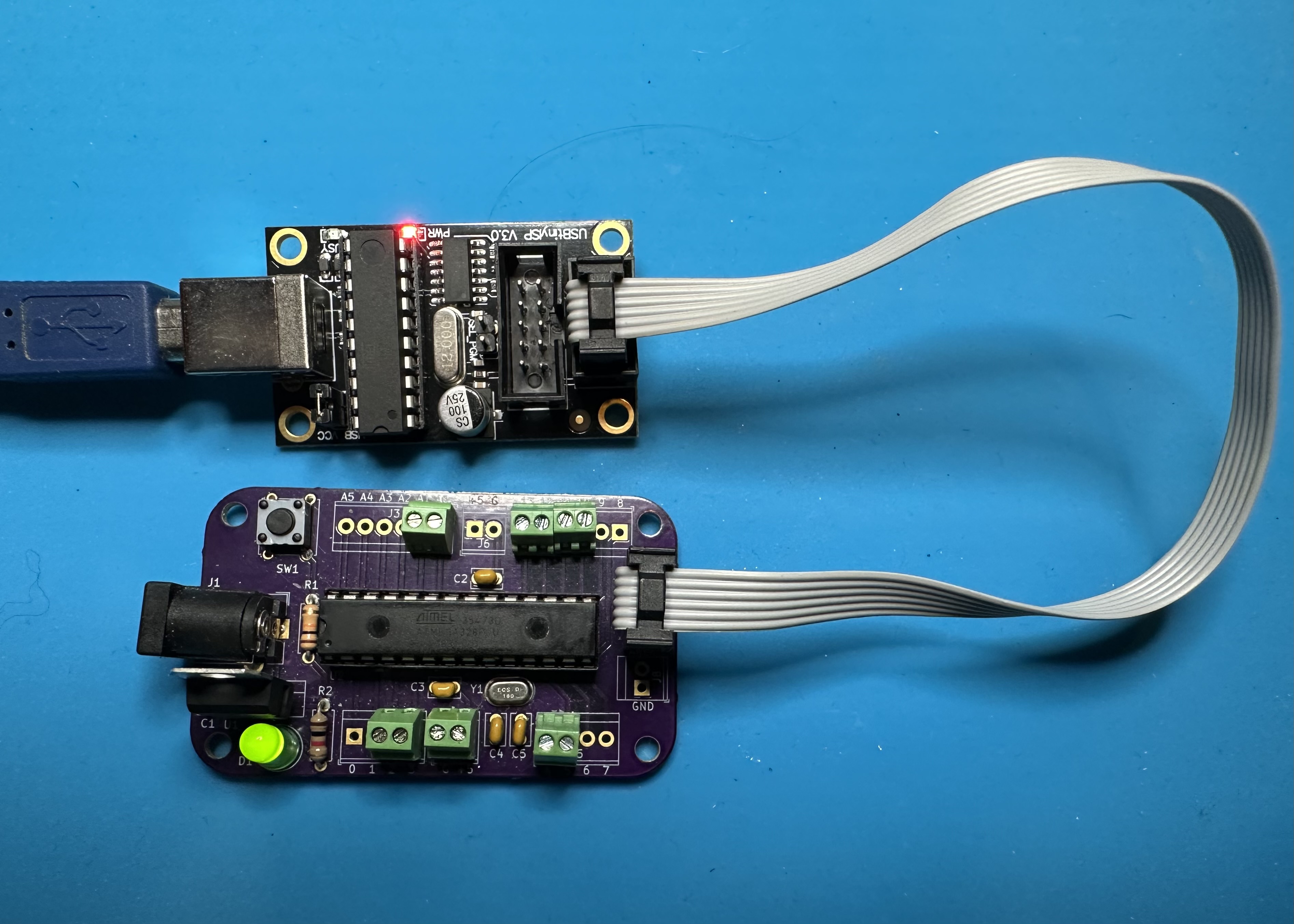
The programming process is exactly the same, except that we need to change the programmer: From the menu: Tools → Programmer → USBTinyISP. Then upload the program using Sketch → Upload Using Programmer.
The only issue that I've noticed with the USBTiny programmer is that the program upload time is significantly longer than when using the Arduino as a programmer. Usually, upload time should not be a big issue.
If you plan to do a lot of embedded-systems development, it is probably worthwhile to have a dedicated programmer.